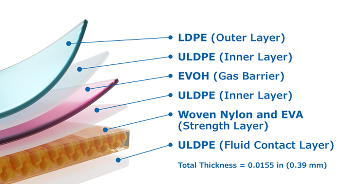
Figure 1: Sterilizing filter systems
Single-use components and systems have been incorporated into many bioprocesses as an alternative to cleanable, reusable systems. A wide range of publications have detailed the reasons for this trend toward a single-use approach. Justification in many cases comes from process-specific benefits such as increased manufacturing flexibility — especially for contract manufacturing organizations (CMOs) — enhanced sterility assurance, elimination of cleaning, reduced capital investment, faster processing times with increased productivity, faster start-up, and other benefits (1).
One critical factor in the application of single-use technology for biopharmaceutical manufacturing has been a need to design and develop components that fully satisfy the performance, functionality, and validation requirements for user process systems. Meeting this requirement is particularly difficult for complex equipment such as bioreactors (1). Here, we discuss how the challenge can be addressed from a systems engineering point of view. Pall’s research and development program included the following key elements during development of the Allegro STR 200, STR 1000, and STR 2000 bioreactors:
a systems engineering approach to design and develop single-use stirred-tank bioreactors incorporating a cubical biocontainer
computational fluid dynamics (CFD) modeling studies showing good mixing performance with the cubical design — matching that for the typical cylindrical format of stainless steel bioreactors
ease-of-use considerations.
Design Considerations
When designing a single-use alternative to an existing cleanable component, one simplistic approach would be to develop a version with similar form, fit, and function that incorporates disposable materials. For some products, that may be possible. For instance, a sterilizing filter system containing a filter cartridge in a stainless steel housing can be replaced by a disposable single-use capsule filter containing a similar type of cartridge inside a plastic housing (Figure 1). Even in that example, however, it may be necessary to modify the filter cartridge’s materials of construction to provide gamma-radiation resistance needed for presterilized single-use products.
For more complex components such as bioreactors, fundamental changes in design and engineering may be necessary. That gives product designers and developers the opportunity to create innovative designs that could enhance performance over traditional cleanable systems while offering practical benefits such as faster system set-up and improved product handling.

Figure 2A: Pall Allegro STR 200 bioreactor components
Design Approach
The first consideration in the design of this bioreactor was to apply systems-engineering principles to ensure robust and reliable performance. Such an approach requires excellent bioprocess, mechanical, production, and control engineering along with ergonomic considerations to ensure easy assembly and efficient operation of the equipment. That can be followed best by considering the overall layout of a bioreactor and its ancillaries. By focusing on individual components critical to achieving a final design (Figure 2), different considerations can be brought out.

Figure 2B: Pall Allegro STR 1000 bioreactor
Geometry of Biocontainer: Most glass and stainless steel bioreactor vessels are cylindrical, the latter designed with dished heads. Such geometry was required to accommodate high-pressure steam for sterilization, and those bioreactors were designed to pressure-vessel standards that require a rounded shape for enhanced mechanical stability (2).
Thus, cylindrical vessels became the standard geometry for bioreactors. However, increasing acceptance of single-use technology and flexible biocontainers, together with elimination of steam-in-place (SIP) and clean-in-place (CIP) procedures, offers product designers the opportunity to consider alternative geometries. It also allows them to incorporate features that could prove beneficial to performance and other functions.
Assessment of the most suitable geometry for a single-use stirred-tank bioreactor led Pall to choose a square cross-sectional format. We favor this geometry not only for its specific bioprocess engineering features (described below), but also for the following reasons:
Cubical single-use biocontainers have been used for many years in unit operations such as storage, product transfer, and mixing in a broad range of validated pharmaceutical processes.
Pall had already gained valuable experience in the manufacture, supply, and validation of biocontainers with cubical geometry.

Figure 3: Allegro STR 200 System features
Ergonomics of Biocontainer Handling and Protection (Figure 3): Flexible polymeric biocontainer film for single-use used in constructing a stirred-tank bioreactor can be damaged during manufacturing through final installation and operation. Thus, Pall paid special attention to features such as biocontainer geometry, materials of construction, seam welding, and packaging as well as design of the system as an integrated unit. In addition, the design team incorporated special features to facilitate ease of installation and operation and to eliminate risks of operator error (3).
It was evident during this development program that a cubical biocontainer would be easier to fold, protect, and package than a cylindrical format would be. That helps ensure the highest possible integrity of biocontainers during manufacturing, shipping, and installation. The cubical shape also presents distinct faces, which helps guide correct biocontainer alignment and orientation during installation into support hardware. The support hardware and biocontainer were engineered to enable simple installation and biocontainer inflation with minimal need for operator adjustments. That eliminates the inherent risk of damage from manual handling and operator error.
Another critical requirement was to prevent contact between the biocontainer film and other system components, making external rigid protective elements necessary. For example, the Allegro STR 200 system includes a rigid cover to protect its impeller from damaging the film during shipping. On Allegro STR 1000 and STR 2000 systems, a rigid base contains and protects the film during shipping and installation. Additionally, the bottom-entry impeller format helped engineers design compact and protective biocontainer packaging that keeps the impeller and components from damaging the biocontainer.
These bioreactors are designed to enable complete installation and inflation by no more than two operators, with step-by-step instructions and color-coded numbered labels to guide them through the process. Minimal operator intervention reduces the risk of accidental damage. The front doors open fully to allow easy access during installation. The door lock controls are based on fluid levels to prevent accidental opening of bioreactor when it is full of liquid. Single-use sensors are incorporated where available to eliminate installation, cleaning, sterilization, and calibration checks. For reusable probes, bellows were designed for aseptic insertion.
Functional Features
Impeller System: To meet bioprocess demands, the choice of impeller is critical to bioreactor design. This component must be able to impart enough power into cell culture medium to enable sufficient mass transfer and satisfy cellular oxygen demands while maintaining good media mixing and homogeneity. In this case, the impeller system design and location had to enable both the ergonomics associated with using a cubical biocontainer and the ease of installation and packaging.

Figure 4: Pitched-blade impeller
Impeller Type: The preferred impeller type identified from published literature (2, 4) was a pitched-blade design (Figure 4). This type is common in bioreactors used for animal-cell culture because it is considered less likely to cause shear damage with optimal blade diameters and agitation speeds. A pitched-blade impeller with an appropriate blade configuration also balances axial and radial flow.
Blade Geometry: The geometry of this pitched-blade impeller was designed specifically to optimize performance in a cubical bioreactor. The large area and 45° pitch angle of the three blades generates a strong up-flow for efficient air dispersion and gas recirculation, a property of particular importance for dense cell cultures that require high rates of oxygen mass transfer and carbon dioxide stripping (2, 4).

Figure 5: Dimensional representation of a bioreactor
Impeller Diameter: The ratio of impeller diameter to bioreactor side-length (D/T) is an important parameter (Figure 5) that affects both flow pattern and power input. For 200-L Allegro systems, the D/T ratio was set to 0.5, which for a given specific power input (W/kg) ensures that mixing times are shorter than for smaller impellers. Homogeneity is improved during pH control, and sparged air is dispersed more efficiently (4, 5).
Impeller Clearance: The ratio of impeller clearance (C) from the bottom of a bioreactor (Figure 4) to fluid height in the bioreactor (H) affects flow patterns and mixing. The C/H ratio in mixing systems typically ranges from 1/3 to 1/6. For Allegro STR 200 bioreactors, a ratio of 1/4 was established as the optimum value. That takes into account the need to maintain good axial flow and adequate mixing at both minimum (60 L) and maximum (200 L) working volumes.
Pumping Direction: The ability to operate an impeller for up-flow or down-flow pumping is an important requirement and was engineered into this system by means of a bidirectional drive motor. The 45° pitched-blade impeller ensures equal pumping rates in either direction. For most animal cell cultures, Allegro STR bioreactors would be programmed for up-flow pumping. But its down-flow capability can benefit adherent-cell cultures on microcarriers, where downward flow enables suspension of the microcarriers at low speeds with low specific power input.
Drive System: For this impeller’s drive system, the design team chose a bottom-entry drive shaft over a top-entry option. The shorter shaft for bottom entry reduces bending moments under power and imposes less stress on drive shaft bearings and dynamic seals for a sterile barrier. As mentioned above, a shorter shaft also allows for more compact packaging and minimizes the risk of container damage.
Speed and Specific Power: The Allegro STR 200 impeller drive system is designed for control up to 150 rpm. In qualification studies for this bioreactor, the power value (P) was measured using a rotary torque transducer fitted to the bioreactor shaft between the impeller and motor (6). The team measured power dissipated by the impeller rotating in air, subtracting the value from that obtained with it rotating in 200 L of water at 37 °C to determine the true power dissipated to the fluid.

Table 1: Overview of specific power input for 200-L, 1,000-L, and 2,000-L Allegro STR bioreactors
Results showed that a specific power input of 0.31 W/kg was obtained in up-flow mode at 150 rpm (Table 1). That specific power level is significantly higher than what is used generally to meet the mass-transfer requirements of currently achievable cell densities. Given the relationship between specific power and kLa, it should ensure that Allegro systems can meet those current mass transfer requirements and higher levels as well. The 1,000-L bioreactors show similar specific power values. The specific power of of the 2,000-L bioreactors is a little lower, but their kLa values are similar because the equivalent maximum volume of air under standard conditions per volume of liquid per minute (VVM) values are maintained so that the linear velocity determining kLa is higher (2, 4).
Headspace Volume in Biocontainer: Expressed as a percentage of the total container volume, headspace volume falls typically in the range of 20–30% for cylindrical bioreactors. Allegro designers set the headspace volume at ~25%, which provides adequate allowance for high hold-up (and possible foaming) associated with high specific power and aeration rates.
Baffles: Initial assessment of bioprocess engineering requirements indicated that good process performance required prevention of strongly swirling flows associated with most unbaffled stainless steel and single-use bioreactors. A square shape greatly reduces swirling flow, but some form of baffling is also required as with cylindrical designs. So the team engineered three protruding vertical metal plates into the stainless steel support hardware. During automated inflation of a biocontainer in situ, these plates form inward protrusions of the biocontainer walls that act as efficient baffles. Such a design eliminates the need for customized shaping and welding of flexible side walls during manufacture and maximizes biocontainer strength, integrity, and robustness.
The design of those metal plates and the resulting internal baffle profile — along with the square shape of the biocontainer — produce flow patterns comparable to those in traditional baffled cylindrical bioreactors. Such flow patterns have been confirmed in subsequent qualification studies (5, 6). Tests of Allegro STR bioreactors also demonstrated that even at higher specific power inputs (P/V ≤ 0.31 W/kg) and agitation speeds (≤150 rpm) swirling flow and bubble entrainment from vortexing remained minimal. Those flow patterns and P/V values ensure excellent homogeneity and mass transfer characteristics (5, 6, 9).

Figure 6: Aspect ratio of a square cross-section Allegro STR bioreactor compared with a cylindrical bioreactor of similar volume
Aspect Ratio: A cubical biocontainer with aspect ratio H/T = 1 has a similar volume to the cylindrical format with a ratio >1 (Figure 6). Because aspect ratios >1 can lead to poor homogeneity at the top surface (2, 4), the cubical format’s lower aspect ratio with its reduced fluid height provides for improved mixing. Such an improvement is of particular benefit for preventing local pH spikes associated with pH control in high–cell-density cultures.
In addition, a low aspect ratio increases the ratio of liquid surface area to volume, so the cubical format provides a greater headspace mass transfer capacity. That could eliminate the need for continuous sparging at the start of a run in some applications — e.g., if a cell line (especially in microcarrier applications) is susceptible to damage by sparging and bursting air bubbles. Minimal sparging also benefits stem cell cultures with very low oxygen demands (7). In addition, a greater surface area enhances CO2 stripping.
Finally, a low aspect ratio provides an ergonomic advantage by minimizing work-at-height issues, e.g., related to manual manipulation of tubes, fixtures, and fittings at the top of the bioreactor or working in areas with reduced head room.

Table 2: Overview of kLa values for 200-L, 1,000-L, and 2,000-L Allegro STR bioreactor
Sparging: Regarding the design and flow capacity of the Allegro STR sparging system, the team took into account requirements for sufficient air flow to achieve required oxygen mass transfer rates and requirements for effective CO2 stripping. When necessary, the latter depends heavily on sparging flow rate. So a ring sparger was designed with ports of suitable size and number to achieve high flow rates (≤0.2 vvm) without excessive linear velocities (5). The system produces relatively large bubbles, which are less likely to damage cells than are small bubbles (4) while maintaining high oxygen transfer through adequate specific power and sparge rate. For Allegro STR systems, even the lowest maximum kLa O2 value — 30 h–1 in the Allegro STR 2000 model (Table 2) — is more than sufficient for most cell culture processes to date.
For high pCO2 levels, sparging in Allegro STR bioreactors (through either the ring or an optional open-pipe sparger) generate high CO2 stripping rates of 3–6 mol/L/d at aeration rates ≤0.1 vvm (5, 9). Optimal CO2 levels vary by cell line (9). Also, because the optimal level of CO2 varies by cell line (9), the cubical geometry can offer greater opportunity for effective CO2 stripping and control of pCO2 over a broad range of cell culture applications.
Together with a separate open-pipe sparger, the high kLa O2 values in Allegro STR bioreactors eliminate the need for microspargers. The latter not only can lead to high pCO2 values, but also increase foam production and cell damage from small bubbles, which negatively affects cell growth (4).
Container Venting: When replacing a steam-sterilizable, pressure-rated bioreactor with a single-use, flexible-film, low-pressure vessel, users must carefully reassess their venting requirements. Sparging of a stainless steel bioreactor can generate foam, aerosolized media, and condensed water vapor that can accumulate in the hydrophobic vent filter, potentially restricting air flow and increasing pressure inside the bioreactor. In a pressure-rated stainless-steel system, that pressure increase can be tolerated, and a modest backpressure may not affect sparging and cell culture performance seriously. However, for a single-use, low-pressure system, backpressure must be prevented by modification of the vent filtration system.
To ensure minimal back pressure in the biocontainer, the Allegro design team selected vent filters that would provide low differential pressure at maximum sparging rates. Vent-filter heater jackets also were developed for placement around the filters, maintaining them at a sufficiently elevated temperature to evaporate all liquid entering the filter housing.
Hydrophobic vent filters usually contain a pleated polytetrafluoroethylene (PTFE) sterilizing-grade membrane. But such filters are unsuitable for single-use systems because PTFE is not resistant to the gamma radiation required for system sterilization. For that reason, the vent filter is made of a pleated PVDF membrane that is resistant to gamma radiation.
To confirm suitability of the vent filter system, filter life tests were performed for ≤45 days of continuous use under process conditions and worst-case maximum–flow-rate conditions. Results showed no filter blockage or condensate-related pressure build-up.
Scalability: The need to make a single-use bioreactor system scalable was a particular challenge in this design and development program. Pall focused on critical scaling parameters such as specific power input, mass transfer, aspect ratios, and stripping. Measurement and control systems would need to ensure that conditions the cells experience within these bioreactors are as similar as possible from size to size.

Table 3: Overview of engineering parameters of 200-L, 1,000-L, and 2,000-L Allegro STR bioreactors
Comparative studies using a Chinese hamster ovary suspension (CHO-S) cell line in Allegro STR 200 and 1000 systems and a 10-L reusable glass bioreactor showed similar performance across all three systems for cell density and viability, monoclonal antibody (MAb) productivity, pH and DO2 control, glucose consumption, and lactate profile (10). Operational parameters and culture performance all closely matched and fell within the desired range for the cell line, confirming scalability of the single-use system up to a volume of 1,000 L. The basic design and engineering features of the Allegro product range now have been extended into a 2,000-L capacity system. Table 3 summarizes the engineering parameters for Allegro STR systems.

Table 4: Geometries of cubical and cylindrical biocontainers
Comparing Cubical and Cylindrical Bioreactors
Using a cubical rather than a cylindrical bioreactor has certain basic advantages as described above. To demonstrate similar mixing in both types, a computational fluid dynamics (CFD) modeling study was carried out on an Allegro STR 200 bioreactor. Vessel geometries were created using Ansys DesignModeller parametric geometry software and meshed using Ansys meshing tools. The resulting mesh was exported to the Ansys Fluent program for performing calculations. Mixing simulations for the two geometries used the same impeller with similar baffling dimensions and aspect ratios (Table 4).

Figure 7: Fluid velocity simulation for cubical geometry at agitation speed of 25 rpm
Flow Patterns: Figure 7 shows predicted flow patterns for a cubical geometry. The impeller discharged fluid in up-flow mode at a 45° angle. When that fluid impinged against the biocontainer wall, some was driven upward toward the surface at relatively low velocity while the rest diverged downwards, with a significant amount then sucked back by the impeller.

Figure 8: Fluid velocity simulation for cylindrical geometry at agitation speed of 100 rpm
Those patterns indicate both axial and radial dispersion below the impeller but predominantly axial dispersion above the impeller. In both cubical and cylindrical geometries, orbiting fluid was present at the impeller tips.
For the cylindrical geometry, a similar flow pattern was predicted at 100 rpm (Figure 8). The flow patterns are very similar to those found experimentally with up-flow, wideblade “elephant ear” impellers (11).

Figure 9: CFD-predicted mixing times versus agitation speed
Mixing Time: After establishing a simulated flow field, mixing simulations were performed based on the addition of 100 mL of a sodium chloride tracer solution at a specific location on the fluid surface. Subsequent distribution of the tracer was computed, with mixing time defined as how long the fluid takes to reach 95% homogeneity at the location of two fictional probes (Figure 9).

Figure 10: Mixing times determined using a conductivity method for the 200-L bioreactor
Only minor differences were seen between the cubical and cylindrical bioreactors at 50 rpm and higher. For a cubical 200-L system, the CFD-predicted mixing times were very similar to those obtained in experimental studies using a conductivity method (5), except at the slowest speed of 25 rpm (Figure 10). The experimental result was more in line with a predicted time for the cylindrical vessel. The reason for that outlying CFD result at 25 rpm is unclear. But for speeds used during culture, the CFD and experimental results are in reasonable agreement.

Figure 11: Mixing times determined using a pH method for Allegro STR bioreactor range
Mixing time also was measured for the full Allegro STR bioreactor range using a pH method at maximum agitation speed (Figure 11). Mixing times increased from 11.4 to 16.0 seconds from the 200-L bioreactor to the 2,000-L bioreactor, as expected by theory (2, 4). No dead zones were observed across the fluid domain.
Impeller Power Number and Specific Power Input: The power input P at the impeller was calculated using this equation: P = 2πNM, where N = impeller rotational speed (rev/s), and M = impeller torque (Nm) obtained from the CFD based on impeller stresses. The impeller power number was then determined from: Po = P/(ρN3 [D]5), where D = diameter of impeller (m) and ρ = density of water (kg/m3).

Figure 12: Computed impeller power numbers and Reynolds numbers
Computed Po values are shown for the full range of agitation speeds of the 200-L cubical bioreactor and the cylindrical bioreactor plotted against the Reynolds number, Re = ρND2/µ (Figure 12). The computed values were relatively constant, as they should be, for Re > ~104 for both bioreactor shapes at a value of 1.5. Because the power number depends on the flow pattern, this confirms the similarity of patterns in both bioreactors. Furthermore, computed power-number values are in good agreement with an experimentally determined value of 1.3 (5) for the Allegro STR 200 bioreactor based on torque meter readings. Such agreement between CFD and experimental power numbers is quite typical.

Figure 13: Theoretical specific power input at different agitation speeds
From the power number, the specific power input P/V (W/kg) can be determined. This is of particular interest because it generally changes little, if at all, across scales — and it is a major determinant in oxygen transfer rates and mixing time. Figure 13 gives CFD values for the cubical 200-L and cylindrical bioreactors. Those data show <5% difference. Figure 14 shows the experimental values along with agitator tip speeds. By comparing the two figures, we can see <10% variation in P/V up to 125 rpm and 16% variation at maximum agitation speed.

Figure 14: Specific power values and tip speeds at different agitation speeds
Addressing Cell Damage Concerns
The possibility of shear damage to cells usually is related to tip speed or specific power input (4, 12). A typical maximum tip speed suggested to prevent such damage during cell culture in bioreactors is ~1.5 m/s (12). However, no theoretical reason or experimental evidence supports that value. Some researchers have reported values well over 1.5 m/s without cell damage in large-scale cell culture (13). Much lower values are available in the cubical 200-L bioreactor (Figure 14). An agitation speed of 100 rpm gives a tip speed of 1.5 m/s at a specific power of ~0.1 W/kg, which is well above the P/V described in literature as necessary for successful large-scale culture (4).

Figure 15: CHO-S viable cell densities and viabilities over time in an Allegro STR 200 bioreactor
An agitation speed of 80 rpm for the Allegro STR 200 bioreactor gave a tip speed of 1.2 m/s and a specific power value of 0.055 W/kg in the up-flow mode (14, 15). An aeration rate of 0.05 vvm was used for a 200-L culture volume. Under those conditions, high cell densities and viabilities could be obtained (Figure 15). In addition, bench-scale studies with 1.8-m/s tip speeds showed no negative effects on cell culture.

Figure 16: Cell culture performance and scalability
Figure 16 shows that equivalent cell culture performance is obtained in the cubical 1,000-L bioreactor (10). These findings confirmed that the design and engineering of the drive system and impeller could provide sufficient agitation and specific power to meet varying demands of animal cell culture applications, with potentially more in reserve for use in cultures with cell recycling.
A modern theory for damage to a range of cell types, including those on microcarriers, suggests that it occurs when cells are larger than the Kolmogorov eddy size, λK. The value of λK can be calculated from the CFD computed average energy-dissipation rates and the ratio of the maximum local value compared to the average, ϕ. It’s difficult to calculate such values accurately with CFD, but experimental work for impellers of the type and D/T ratio used here gives a value of ~15 (16).
The relationship for calculating λK is described by

where ν is the kinematic viscosity and εT is the specific power input in W/kg (1 W/kg = ~103 W/m3 for fluids of a density similar to cell culture media).
To prevent damage, clearly λK must be >~20 µm. However, at the maximum speed available, εT = 0.4 W/kg and λK = ~35 µm. Thus, damage should not occur (4). Recent studies at values up to 1,000 W/m3, in one case using a dual–pitched-blade impeller and the other using Rushton turbines, have showed no deterioration in process performance or product quality, including glycosylation (17).
The potential always remains for damage from sparging, but culture media these days come with an adequate level of Pluronic F-68 surfactant to prevent such damage, so that too should be no problem (4, 19). However, with insufficient gas flow, the level of pCO2 can build up to an unacceptable level. CO2 values >~150 mm Hg have been reported to compromise culture performance (18, 19). The sparge rate in Allegro bioreactors should be sufficient to prevent that problem.
Stem cell cultures may present difficulties. But here again, recent use of bioreactors with impeller and vessel configurations that are effective for suspension cultures have provided good cell growth and quality at the minimum speed required for suspension (NJS)(7), which is typically the lower speed available in the Allegro STR range. In situ cell detachment is effective for harvesting, provided a short period of much higher-intensity agitation can be used, as is also available with these bioreactors (20). That technique also may be useful for passaging when animal cells are cultured on microcarriers for vaccine production.
The Next Step Forward
The approach to design and development of single-use stirred tank bioreactors described herein was based on good engineering principles. Focusing on every critical component and function has ensured that the final product can provide a viable alternative to traditional stainless steel cleanable bioreactors. A traditional cylindrical biocontainer geometry can be replaced by a single-use, cubical format. In combination with a purpose-designed impeller, baffles, and sparging system, that can give equal or enhanced performance over an equivalent reusable bioreactor.
Computer modeling studies have confirmed comparable specific power input, energy dissipation rates, and mixing times that match the cubical bioreactors’ performance to that of their cylindrical counterparts. It has also been possible to ensure robustness and integrity of the single-use system by incorporating additional features associated with manufacturing, handling, and installation procedures.
Engineering of the single-use Allegro STR bioreactors also has taken into consideration the need for scalability. Scalable performance has been demonstrated from a benchtop cylindrical 10-L bioreactor to the 200-L and 1,000-L cubical bioreactors. Based on the success of this fivefold scale-up and the underlying use of a modern bioreactor design and control concept, validation of further scale-up by a factor of two (currently ongoing) seems assured.
Bioreactors represent just one of many unit operations within a complete upstream and downstream bioprocessing system. The availability of a disposable alternative to traditional reusable stainless steel bioreactors is another step forward in the integration of single-use unit operations into a fully disposable process system.
References
1 Rader RA, Langer ES. Upstream Single-Use Bioprocessing Systems. BioProcess Int. 10(2) 2012: 12–18.
2 Nienow AW. Stirring and Stirred-Tank Reactors. Chem. Ing. Technik. 86, 2014: 1–13.
3 USD 2923. Allegro STR 200 Single-Use Stirred Tank Bioreactor. Pall Life Sciences: East Hills, NY, 2014.
4 Nienow AW. Reactor Engineering in Large Scale Animal Cell Culture. Cytotechnol. 50, 2006: 9–33.
5 Isailovic B, Rees B, Kradolfer M. Fluid Dynamics of a Single-Use Stirred Tank Bioreactor for Mammalian Cell Culture. BioProcess Int. 13(8) 2015: 60–66.
6 USD 2980. Application Note: Characterization and Engineering Performance of the Allegro™ STR 200 Single-Use Stirred Tank Bioreactor System. Pall Life Sciences: East Hills, NY, 2014.
7 Rafiq QA, et al. Culture of Human Mesenchymal Stem Cells on Microcarriers in a 5-L Stirred-Tank Bioreactor. Biotechnol. Lett. 35, 2013: 1233–1245.
8 USD 3136. Application Note: Characterization and Engineering Performance of the Allegro™ STR 1000 Single-Use Stirred Tank Bioreactor System. Pall Life Sciences: East Hills, NY, 2014.
9 Goudar CT, Piret JM, Konstantinov KB. Estimating Cell Specific Oxygen Uptake and Carbon Dioxide Production Rates for Mammalian Cells in Perfusion Culture. Biotechnol. Progr. 27, 2011: 1347–1357.
10 USD3135. Application Note: Cultivation of CHO Cells in Allegro™ STR 1000 Single-Use Stirred Tank Bioreactor System. Pall Life Sciences, East Hills, NY, 2014.
11 Zhu H, et al. Mixing Studies in a Model Aerated Bioreactor Equipped with an Up- or Down-Pumping “Elephant Ear” Agitator: Power, Hold-Up and Aerated Flow Field Measurements. Chem. Eng. Res. Des. 87, 2009: 307–317.
12 Varley J, Birch J. Reactor Design for Large Scale Suspension Animal Cell Culture. Cytotechnol. 29, 1999: 177–205.
13 Hoeks FW, et al. Industrial Applications of Mixing and Mass Transfer Studies. Alvin W. Nienow’s Day: Stirred, Not Shaken Symposium. Birmingham, UK, 2004.
14 Isailovic B, Rees B, West A. Performance of a Single-Use Stirred Tank Bioreactor for Mammalian Cell Culture. BioProcess Int. 14(8) 2016: 58–63.
15 USD2926. Application Note: Cultivation of CHO Cells in Allegro™ STR 200 Single-Use Stirred Tank Bioreactor System. Pall Life Sciences: East Hills, NY, 2014.
16 Zhou G, Kresta SM. Impact of Tank Geometry on the Maximum Turbulence Energy Dissipation Rate for Impellers. AIChE J. 42, 1996: 2476–2490.
17 Nienow AW. Letter to the Editor Re: Paper “Development of a Scale-Down Model of Hydrodynamic Stress to Study the Performance of an Industrial CHO Cell Line Under Simulated Production Scale Bioreactor Conditions. J. Biotechnol. 164, 2013: 41–49.” J. Biotechnol. 171, 2014: 82–84.
18 Sieblist C, et al. Insights into LargeScale Cell-Culture Reactors II. Gas-Phase Mixing and CO2 Stripping. Biotechnol. J. 6, 2011: 1547–1556.
19 Nienow, AW. Chapter 5: Mass Transfer and Mixing Across the Scales in Animal Cell Culture. Animal Cell Culture, Cell Engineering 9. Al-Rubeai M, Ed. Springer International: Cham, Switzerland, 2015: 137–169.
20 Nienow, et al. A Potentially Scalable Method for the Harvesting of hMSCs from Microcarriers. Biochem. Eng. J. 108, 2016: 24–29.
Corresponding Alvin W. Nienow, FREng, BSc(Eng), PhD, DSc, Dhc, CEng, CSci, FIChemE, HonMCzSChE, is emeritus professor of biochemical engineering at the University of Birmingham, UK; [email protected]. Bojan Isailovic, PhD, and Timothy A. Barrett, PhD, are principal engineers in research and development at Pall Life Sciences.