Preuse, Poststerilization Filter Integrity Testing for Single-Use and Stainless-Steel InstallationsPreuse, Poststerilization Filter Integrity Testing for Single-Use and Stainless-Steel Installations
October 16, 2014
https://bioprocessintl.com/wp-content/uploads/2014/10/102014_Stering.mp3
According to current European Union good manufacturing practice (EU GMP), integrity testing of sterilizing-grade product filters should be performed preuse poststerilization (PUPSIT) and immediately after use. In addition, PDA’s Technical Report 26 states that preuse integrity tests are preferably performed after filter sterilization. Performing an integrity test of an already sterilized product filter in-line requires wetting the filter while maintaining the downstream side sterile. The test gas must also be evacuted on the downstream side throughout testing maintaining sterility. The upstream side also must be protected from uncontrolled bioburden, which generally is understood as maintaining sterility of the upstream side by using sterile water for wetting and a sterilizing barrier between the integrity tester and the filter to be tested.
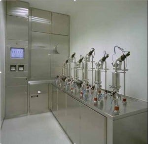
Photo 1: The filter management system (FMS)
The drawback of performing integrity testing on a sterilized filter in-line is that rather than increasing process safety, it can increase risk from operator-handling errors and additional filters. The installation also becomes more complicated. The most common method of maintaining sterility on the downstream side throughout wetting and during a test is to use a sterilizing-grade filter, which has to be tested to prove maintained sterility. In addition, the supply of WFI from the upstream side typically requires a sterilizing-grade filter, which then has to be integrity tested to demonstrate maintained sterility.
Taking into account all filters required to protect a process filter and a process line for implementing preuse poststerilization integrity testing, at least three to four additional integrity tests must be performed. In addition to the increase of risk from these filters, there is significant down time of the installation.
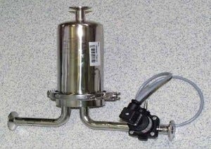
Photo 2: Housing with downstream valve
Here I present an engineering approach for preuse poststerilization integrity testing that already has been implemented on several production sites. Instead of blocking the process line, filter integrity is performed in a filter’s housing (in situ) on an automated test bench (off line). This in-situ off-line approach strongly reduces the downtime of a process line as a filter in its filter housing is being tested, while an already integrity tested identical filter in an identical filter housing are installed on the process line.
Filter Management System
Rather than installing a new filter to be used in its filter housing on a process line, the filter is installed in its filter housing on a test bench (Filter Management System, FMS) (Photo 1).
A fully automatic process is launched in the following steps:
Steaming the filter in its housing (after preflushing with water, if required)
Precooling the filter and housing under sterile conditions
Wetting with sterile water and draining the filter under sterile conditions
Integrity testing the filter under sterile conditions (with temperature survey if defined in the user requirement specifications)
Drying the filter and its housing under sterile conditions • Closing upstream and downstream valves included on the housing (Photo 2, only downstream valve is shown).
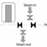
Figure 2: Downstream sterilization separate from the installation
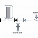
Figure 1: Downstream steam sterilization with the installation
The closed filter housing (including the integrity-tested sterilizing-grade filter) can then be installed on a process line. The downstream connection is steam sterilized either together with the installation (Figure 1) or separately before the valve is opened (Figure 2). The upstream connection also can be steam sterilized. Because every filter housing has got an identical “twin-brother housing,” one housing may be in use while the other is processed on the FMS with a new filter (or reused in case of a hydrophobic vent filter).
Because the filter is dried after the integrity test and kept sterile by the closed valves, it can be put on stock before being used in the process. Figure 3 shows the life cycle of a filter in its filter housing.
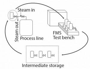
Figure 3: Life cycle of a filter in its housing
Steaming a Filter in Its Housing: The automatic process on the FMS method starts with steaming a filter (preceded by a preflushing of the hydrophilic filter cartridge if required by the filter’s manufacturer). Steaming should be supervised in terms of temperature and time and data recorded in a database. Becasue no additional equipment is steam sterilized with the filter, steaming conditions are obtained with minimal differential pressure applied over the membrane. And because the process is supervised, there is no risk of being outside the filter’s temperature and differential-pressure specifications.
Precooling Filter and Housing under Sterile Conditions: To prevent stress on a filter cartridge (as from fast cooling when flushed immediately with water), the housing is cooled down gently with sterile air to nearly 60 °C. The integrated air filter on the FMS — which is used to supply sterile air — is automatically integrity tested before and after the process, thus ensuring that sterility is maintained.
Wetting and Draining a Filter under Sterile Conditions: After precooling, the filter cartridge can be cooled down by flushing with sterile room-temperature water. Sterile water is obtained by filtering water for injection (WFI) through an integrated sterilizing-grade filter. This filter is automatically integrity tested before and after the process, thereby ensuring that sterility is maintained.
Fully automated flushing implements a higher inlet pressure and back pressure than conventionally used when wetting filter cartridges before integrity testing. The back pressure is obtained by limiting the flow, and the differential pressure over the membrane is kept low for minimal stress on the membrane. This procedure provides more efficient wetting conditions, thus requiring a lower volume of water. Such wetting conditions contribute to process consistency because nearly 90% of all filter-failure claims from customers are a result of inadequate flushing.
If the filter to be tested is a hydrophobic filter, then the filter cartridge cannot be rinsed with water. The filter housing is therefore filled with sterile water to cool it down. The cooling water is then drained, and the filter housing is refilled to perform the water intrusion test (WIT) or water flow test (WFT).
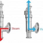
Figure 4: Steam-through connector
Filter Integrity Testing under Sterile Conditions: Integrity is tested according the pressure-drop method, for which the correlation to the integrity test value is explained in PDA Technical Report 26 (1). The filter housing including the filter to be tested is pressurized using sterile air. After a predefined stabilization time at the test pressure, the housing gas net volume is measured using a reference volume. The reproducibility of the net volume value confirms that the correct filter size has been installed in the housing.
After the net volume is measured, the test pressure is restabilized and the pressure drop is measured. During the test, a temperature survey is performed and recorded (if specified in the user requirement specifications) to monitor temperature influences. After the integrity test, a full test report is displayed and recorded in the data system. Printing can be performed locally and/or in a different area as required.
Drying the Filter and Its Housing under Sterile Conditions: After the integrity test, the filter cartridge and the housing are wet. To obtain storing conditions and prevent product dilution, the filter and its housing must be dried. The housing is therefore flushed with warm sterile air, which is evacuated on the upstream side as well as on the downstream side under sterile conditions. As water evaporates, warm air is cooled. The temperature is monitored on the incoming warm air and on the downstream side of the filter. When the temperature difference between the incoming air and the downstream side is smaller than a specific validated value, the filter and housing are dry. Drying process parameters are recorded in the data system for process consistency.
Closing Upstream and Downstream Valves: After storing conditions have been obtained, upstream valves (if defined in user requirement specifications) and downstream valve are closed (default position). This keeps the filter sterile. The housing (and its valves) is then disconnected from the test bench and may be used immediately or put on stock for later use.
Installing a Housing into a Process (Classical Stainless Steel): Because the valves ensure that the filter is sterile, only the connection must be sterilized. Sterilization can be conducted in two ways: either while steaming the whole process line (Figure 1) or by using steam through piping between a sterile housing and the already sterilized process line (Figure 2). The valves of the housing are then opened with compressed air piloted by the local PLC.
Large Housings: Large housings (e.g., multiround) might not be able to be displaced and put on the FMS test bench. So all required items (valves, sterile air, sterile water, and pressure sensors) are brought to the housing. Integrity testing is then started using a local touch panel.
Installing the Housing into a Single‑Use Bag Process Line: Single-use process lines commonly use single-use capsules that cannot be in-line steam sterilized and integrity tested using the FMS test bench. In such case, using a single-use steam-through connector (Figure 4) makes it possible to connect stainless-steel housings to any kind of single-use set-up.
Reducing Process Risk
Many inspectors consider preuse poststerilization integrity testing (PUPSIT) a GMP requirement. However, some users and the PDA PUPSIT task force consider preuse poststerilization testing to increase process risk. The FMS test bench is an engineering way to reduce process risk commonly associated with PUPSIT. The FMS bench can be efficiently implemented only if a process line is designed from the start to integrate special designed housings. The economic viability of the FMS bench is based on the number of housings and number of tests performed per day.
More than just addressing the concerns of PUPSIT, the FMS method can significantly reduce downtime of a process line. No filter will ever block the production line because of integrity testing or required retesting preceded by time-consuming rewetting and error seeking. Based on experience with integrity testing failures and individual cost for process line downtime, a customer-specific return on investment can be calculated to determine whether the FMS is a cost-effective method.
Magnus Stering is product manager for Integrity Testing Solutions, Sartorius Stedim Biotech; [email protected].
You May Also Like
