Scaling Considerations to Maximize the High-Area AdvantageScaling Considerations to Maximize the High-Area Advantage
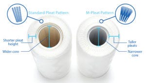
Figure 1: Conventional and M-pleat pattern
Maximizing filtration-area density is a design strategy to minimize filter footprint and improve filtration process economics. Pleated membrane formats commonly are used to achieve that goal for sterilizing-grade filters operating in dead-end mode (also known as normal-flow filtration). Although high-density pleat geometries increase productivity for a device, such formats can present unique challenges. One of the most common concerns is that pleat formats can introduce flow resistance that impedes a device’s filtration efficiency, particularly for high–pleat-density geometries (1, 2). Filtration efficiency can be affected by pleat length, membrane permeability, and thickness and flow characteristics of upstream and downstream supports as well as other aspects of a pleat configuration.
One approach for overcoming those challenges has been the development of an M-pleat pattern that allows for a nearly 100% increase in membrane area over conventional designs (Figure 1). The M-pleat design has been optimized for maximum area density, device manufacturability, and a high level of device robustness. Other improvements include the ratio of long to short pleats, pleat compression, and upstream and downstream support materials (see “Design Improvements” box below). M-pleat designs help address the challenges of filtration efficiency while matching existing cartridge sleeve and length dimensions.
Design Improvements |
|---|
Long and short pleats form an “M” shape. The number of both and the ratio of their lengths can be varied for optimal filtration area. We determined values that resulted in high filtration area and a robust pleat pack. Long to short pleat number ratio is 2 and the short to long pleat height ratio is 0.6. |
Once a pleat pack is created, it can be squeezed to varying degrees to insert it into the supporting sleeve/core annulus (the cage around the pleat pack). The amount of compression affects filter performance. High compression allows for high filtration area. But if the compression is too high, then flow performance can suffer because of the higher resistance to flow in such a tight structure. We reached an optimal balance between both filter attributes. |
Compared with standard-area devices, a high-area design uses thinner support materials, which occupy less volume in a device and thus leave more room for the membrane filter and greater filtration area. |
Ultimately, filter-design efficiency depends on how well a membrane performs when it is in a filtration device. One method of measuring a device’s filtration efficiency is to compare the performance of a membrane in a filtration device with that of one in a flat-sheet format (where the flow resistance is dominated by the membrane itself). The ratio of commercial-scale filter performance to small-scale, flat-sheet performance is often referred to as the scaling factor. Ideally, that should be at or close to one.
The scalability factor of a device must be defined with respect to a set of specified conditions. In particular, there can be a compromise among other filter requirements (including high-area density) and good scalability. Scalability also can be sensitive to filter operating conditions, challenge stream characteristics, and the particulars of a selected filtration endpoint. A filter can exhibit a range of scaling factors depending on the combination of those other conditions.
Here we discuss variations in scalability in newly developed high-area versions of sterilizing-grade filters. We describe a model that was developed to predict filter device efficiency as a function of the filtration properties of a filtered stream. The model can be used to assess which applications can benefit most from high-area pleated devices and which should use conventional pleat configurations.
Our study evaluated filters for scalability against a nonplugging stream (water) and three different plugging streams that represented a wide range of particle-size distributions. We assessed scalability as a function of particle size and degree of plugging. Filters were tested primarily for constant pressure operation and measured for constant-flux operation.
Theoretical Background
Several factors must be considered when scaling from discs to pleated devices. Applicable to all pleated filter devices, these factors include flow resistance from upstream and downstream supports, pressure losses from housings and plumbing, and variability in filter properties, stream characteristics, and operating conditions (3). Although some theoretical treatments of flow restrictions in conventional pleat patterns have been studied, no known similar treatments have been published for the M-pleat pattern evaluated in this work. Here we focus on the effect of the M-pleat pattern on filter performance, because factors such as membrane and process variability are not specific to high-area devices.
Rather than develop a model that predicts the impact of the M-pleat pattern on filter efficiency from first principles, we used a semiempirical approach. Flow resistance associated with the pleat pattern is inferred from clean-water scaling data and then applied to a model that predicts filtration efficiency as a function of membrane plugging.
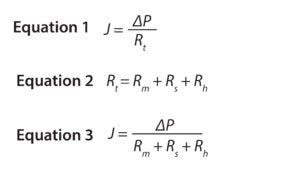 The flux through a filter can be described using Darcy’s law (Equation 1), in which J is the flux, ΔP is the pressure differential across a filter, and Rt is the total resistance to flow. Rt includes flow resistance from the membrane (Rm), upstream and downstream supports (Rs), and filter housing (Rh) (Equation 2). Substituting Equation 2 into Equation 1 gives Equation 3.
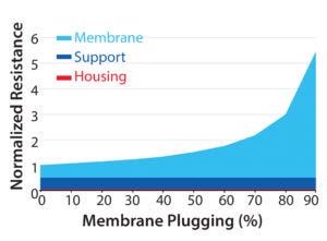
Figure 2: Components of total filtration resistance as a function of membrane plugging
For a plugging stream, Rm will increase with throughput while Rs will be unchanged (assuming that upstream and downstream supports do not plug). Rh will change with flow rate (predictably).
As a membrane plugs, resistance from the membrane becomes an increasingly larger fraction of the total resistance (Figure 2). Rs and Rh decrease relative to Rm as membrane plugging increases and the scaling factor increases with increasing filtrate volume (and degree of membrane plugging).
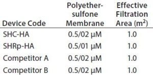
Table 1: Ten-inch cartridges evaluated in this study
Materials and Methods
Membranes and Devices: Four high-area cartridges were evaluated in this study (Table 1). They included 10-inch high-area sterile high-capacity (SHC) (referred to as SHC-HA) and SHC standard-area (SHC-SA) cartridge filters (from MilliporeSigma). Those products contain the same types of membranes: one layer each of 0.5-µm and 0.2-µm polyethersulfone (PES) asymmetric membrane. Standard-area versions of those devices contain about 0.5 m2 of effective filtration area. Two additional 10-inch cartridge filters from different manufacturers also were evaluated. For small-scale tests, 25-mm membrane discs were installed into OptiScale 25 devices (from MilliporeSigma), which contain 3.5 cm2 of effective filtration area.

Table 2: List of challenge streams for throughput tests (PBS = polybutylene succinate)
Challenge Streams: Three challenge streams were used in this study (Table 2) to represent small, medium, and large particle sizes and particle-size distributions (Figure 3). The challenge streams were concentrated to achieve a high degree of plugging (>90% flux decay at <1,000 L/m2 of filtrate) within about 30 minutes at the process conditions.
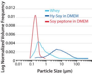
Figure 3: Particle-size distributions of the challenge streams used in this study; particle sizing data were gathered using a Malvern MasterSizer particle size analyzer.
Test Method: Both OptiScale 25 devices and 10-inch cartridges were tested for clean-water permeability at 10 psi (690 mbar) and 21–25 °C. Following the water permeability test, throughput tests using one of the challenge streams were conducted at 10 psi (690 mbar). That throughput testing ran until the membrane permeability was reduced by at least 95% compared with the clean water permeability.
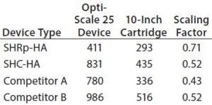
Table 3: Cartridge-to-disc scaling factors for water permeability (LMH/psi)
Results and Discussion
Water permeability data were collected for each membrane and device type (Table 3). For water, scalability factors for three of the four filters tested were about 0.5. The flow resistance from the supports was about the same as that of the membrane, resulting in about a 50% loss in productivity compared with that of the OptiScale 25 device. In the fourth device (SHRp-HA, containing the tighter 0.1-μm membrane) the membrane was responsible for a higher fraction of the total filter resistance, resulting in a higher scaling factor.
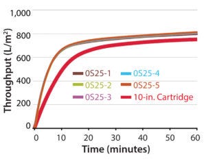
Figure 4: Throughput curves for SHC-HA challenged with soy peptone
Throughput was evaluated using multiple feed streams representing a wide range of particle-size distributions. The soy peptone (papainic digest of soymeal from MilliporeSigma) stream had a relatively small median particle size (about 0.2 µm) and relatively narrow particle-size distribution. This stream would be expected to foul membranes through an internal pore-plugging mechanism. The study found that for this stream, the initial flux-scaling factor was similar to that of water. But as the membrane fouled, the flux-scaling factor converged toward one (Figure 4). That is a result of the membrane becoming an increasingly larger fraction of the total filter resistance as the membrane fouls.
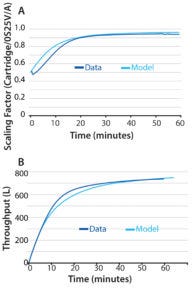
Figure 5: Comparing data and model predictions for filtration of soy peptone with SHC-HA; (A) scaling factor over time; (B) 10-inch cartridge throughput over time.
We plotted scaling factor as a function of filtration time for the SHC-HA cartridge and the model prediction (Figure 5). Figure 6 shows throughput scaling factors for the cartridges tested in this study at 30 minutes filtration time (about 95–99% flux decay). For that stream (using 2 g/L soy peptone), scaling factors are all within about 15% of one (within the approximate measurement uncertainty).
The Hy-Soy T (Kerry) stream had a large particle size and wide distribution. Figure 7 shows throughput and flux decay curves for this stream, and Figure 8 shows scaling factors at 30 minutes. This stream showed initial flux scaling factors as expected (similar to water). But as the filters plugged, the scaling factors diverged away from one rather than converging. That result is explained by the larger particle size in the Hy-Soy T stream. These particles cannot enter the membrane pore structure and therefore accumulate at the membrane surface, forming a cake.
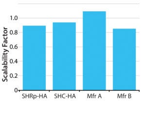
Figure 6: Scaling factors at 30 minutes filtration time using 2 g/L soy peptone
The OptiScale 25 format includes an open space above the membrane surface, resulting in unhindered cake buildup with the Hy-Soy T stream. In a densely pleated format, a nonwoven support is in contact with the membrane surface, bounded by an adjoining pleat, which limits the available space for a cake to form. Furthermore, in a densely pleated format, particles must travel laterally through the nonwoven support before reaching the membrane. Any particle buildup at the entrance to the pleat pack prevents subsequent particles from accessing the membrane surface.
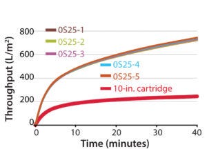
Figure 7: Throughput curves for SHC-HA challenged with Hy-Soy-T
Previous studies have shown that standard-area devices suffer less than high-area devices from large-particle accessibility to the membrane surface (3). As a result, high-area devices may not be preferred to standard devices if challenged directly with a Hy-Soy T (or large particle size and wide distribution) stream. An appropriately sized prefilter removes large particles that would otherwise form a cake on the final-filter membrane surface. With the large particles removed, the throughput advantage of high-area devices can be restored.
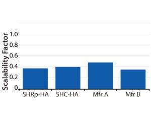
Figure 8: Scaling factors at 30 minutes filtration time using 0.1 g/L Hy-Soy T product
We also tested a whey stream for throughput with intermediate particle size (Figure 9). As with the smaller particle-size stream, the flux scaling factors converged toward one as predicted (Figure 10). Those data demonstrate that for plugging streams in which caking is not a predominant fouling mechanism, high-area devices scale close to one if a high level of plugging is achieved. Alternatively, if the level of plugging is low or intermediate, then the scaling factor also is intermediate between that of what it is with water and one. In such a case, the model described in this study can be used to estimate scaling factor.
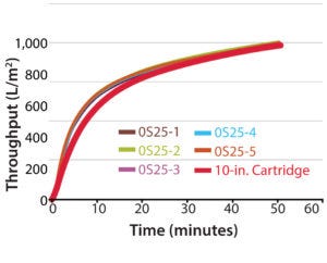
Figure 9: Throughput curves for SHC-HA challenged with whey
Normal-flow filtration often is operated at constant pressure, but constant flow is another common mode of operation. To evaluate scalability for constant-flow operation, we tested an SHC-HA cartridge at a flux of 500 LMH using a whey stream. In that test, the initial ΔP for the cartridge was about double that of the OptiScale 25 devices. But as the membrane plugged and reached the 20 psi (1,400 mbar) filtration endpoint, the pressure profiles of the cartridge and OptiScale 25 devices converged (Figure 11). This trend is similar to that in constant-pressure operation. Results demonstrate that the scalability principles demonstrated for constant-pressure operation also apply to constant-flow operation.
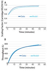
Figure 10: Comparing data and model predictions for filtration of whey with SHC-HA; (A) scaling factor over time; (B) 10-inch cartridge throughput over time
Advantages of Using High-Area Devices
Nonconventional pleat configurations can provide increased filtration areas and greater process efficiencies in cartridge devices. A larger area has the advantage of lower cost per unit of filtration area, and potentially higher productivity per device. In some cases however, a high pleat density within a device can lead to decreased efficiency in use of a contained area.
This study examined a model developed to predict scalability as a function of membrane plugging when caking is not predominant. That model can be used to quantify the advantage of high-area devices for a given set of operating conditions, membrane-fouling properties, and filtration endpoint. It also provides an understanding of mechanisms underlying measured scaling factors.
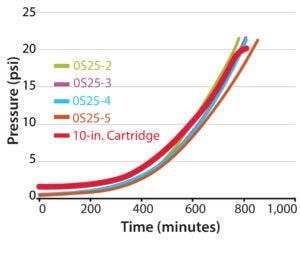
Figure 11: Scalability at constant flow operation for filtration of whey with SHC-HA
We also found that for plugging streams for which caking is not a predominant fouling mechanism, high-area devices exhibited near-linear scalability. This was because, as the membrane fouls, it becomes the dominant resistance to flow. In that circumstance, using high-area devices offers a clear advantage over standard-area devices. An exception to that advantage can come with plugging streams in which caking is the primary fouling mechanism. When particles are larger than membrane pores, the volume available in a dense pleat pattern to form a cake is limited. In such cases, prefiltration is recommended to remove large particles.
References
1 Gollan A, Parekh BS. Hydrodynamic Aspects of Semidense Pleat Designs in Pleated Cartridges. Filtr. Separat. 22(5) 1985: 326–329.
2 Giglia S, Yavorsky D. Scaling from Discs to Pleated Devices. PDA J. Pharm. Sci. Technol. 61(4) 2007: 314–323.
3 Giglia S, et al. Improving the Accuracy of Scaling from Discs to Cartridges for Dead-End Microfiltration of Biological Fluids. J. Membrane Sci. 365(1) 2010: 347–355.
Corresponding author Sal Giglia is R&D manager, filtration applications, at MilliporeSigma, 80 Ashby Road, Bedford, MA 01730; 1-781-533-2564; [email protected]. Songhua Liu and Ryan Sylvia are both development engineers at MilliporeSigma.
You May Also Like


