A UF–DF Screening System for Bioprocess Development: Efficient and Cost-Effective Process Fit and Scale-Up to ManufacturingA UF–DF Screening System for Bioprocess Development: Efficient and Cost-Effective Process Fit and Scale-Up to Manufacturing
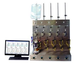
Photo 1: Five-station tangential-flow filtration (TFF) screening system design agreed upon by the collaborators
Ultrafiltration and diafiltration (UF–DF) of therapeutic proteins are performed in either tangential or crossflow mode using membrane filters. UF–DF plays a critical role in both downstream and upstream processes for the biopharmaceutical industry (1). In upstream production processes, classical tangential-flow filtration (TFF) or alternating tangential-flow (ATF) systems are used in high–cell-density perfusion for protein expression by cell culture (2). TFF is used in downstream processing for UF–DF and concentration of therapeutic proteins. TFF unit operations are common in protein purification because of their scalability and amenability to continuous processing (3–5). Typical TFF process development involves optimization of transmembrane pressure (TMP), permeate flux, feed flowrate, buffer compositions, and the interdependence of all those parameters. Optimization requires a broadly defined design space and many experiments needing significant time and resource investments.
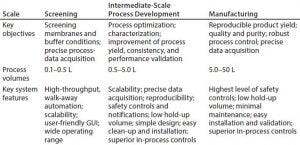
Table 1: Key objectives and system requirements for UF–DF; GUI = graphical user interface
With speed to first-in-human initiatives leading to shrinking timelines in early process development, the demand for enhanced throughput has increased significantly in recent years. Expedited timelines and minimal material availability in early phases complicate process development of TFF. For increased throughput on chromatography-based unit operations, options are available such as high-throughput chromatography and robotic screening tools such as TECAN systems. However, few such tools are available commercially for filtration unit operations. The few systems on the market require users to adapt to device requirements, leaving very little flexibility to work. It is important that such tools provide as smooth a flow as possible, with accurate information for scaling up TFF processes to intermediate (for further process development/verification) and then manufacturing scales (Table 1).
Early phase process development verifies initial platform fit assessment of a downstream process and helps companies determine whether downstream process modifications are needed. Early phases of process development often require rapid decisions made regarding choice of membrane types and UF–DF process conditions. Although the objectives for early phase development primarily focus on determining platform suitability of process conditions for a given molecule, late-stage UF–DF development focuses on more detailed process characterization and risk assessment. That includes improving process yield, throughput, and consistency as well as performance validation (reproducibility, sensitivity, and lot-to-lot variations) with a representative scale-down model. For a suitable scale-down model, it is critical to distinguish between system- and process-related variations in UF–DF. For process development or characterization, superior control of system parameters helps developers differentiate between system- and process-related responses.
Here we report the design and development of a fully automated TFF multistation consisting of five independently operated TFF stations with advanced system controls that can run in parallel for screening UF–DF process conditions (Photo 1).
Benefits of Laboratory-Scale Process Automation
A typical laboratory-scale TFF process is semiautomated with a few pumps, some dial pressure gauges, a scale, and manual valves. Integrating system parts from multiple suppliers poses a challenge. Data logging requires an operator to monitor and export process data manually to third-party software for analysis, often with the challenge of merging data from different sources that have uncoordinated time stamps. In a process that can have a run-time of several hours, varying a range of conditions with multiple runs can consume many personnel resources, especially if run manually. Therefore, automation is critical to enable process optimization while minimizing key personnel resources.
We believe that to create a more efficient development operation, we need a system with automated process steps that have defined endpoints, control of key process-independent variables throughout a process, calculation of key process values (e.g., ∆P, TMP, and flux), alarm settings that shut down the pump, data-logging and real-time trend viewing. By its nature, such an automated system would provide benefits of minimal user interaction. With automated data-logging, user focus can be placed on analysis rather than data collection.
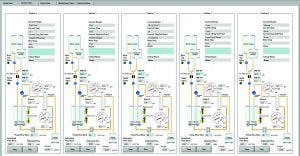
Photo 2: Five-station TFF screening system’s graphical user interface (GUI) with process schematic and system control ability
Creating the TFF Screening System
In discovery and early phases of biologics process development, low expression titers typically limit availability of therapeutic protein. Bristol-Myers Squibb (BMS) wanted an automated TFF system for screening at these early phases when only small amounts of proteins are available. We believed it should have the ability to generate data from small-scale processes that could provide reliable information for scaling up. To address these challenges and add increased throughput capability for fast and efficient process development, BMS collaborated with PendoTECH (an industry supplier of downstream process development systems) to develop a multistation medium-throughput TFF screening system.

Table 2: Designed process capabilities
Here we report on development of a fully automated system with features as listed above. A parallel TFF screening system consisting of five independently operated stations was designed and built based on BMS requirements for typical early phase TFF process-development goals. The multistation parallel TFF system described herein can provide ≤70% reduction in material requirements, speed up design-space development for nonplatform molecules, and potentially reduce development times by 50–80% (Photo 2).
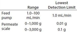
Table 3: Feed pump and permeate scale sensitivity
Defining User Requirements: Before establishing the requirements of a new TFF screening tool, we conducted a thorough market survey of available options and their capabilities and weighed their relative merits and limitations. Most systems did not support parallel screening and required too many manual interventions because they lacked high-level automation. To address the disadvantages of existing equipment, several requirements shaped development of the parallel TFF screening system.
Along with the process capabilities outlined in Table 2 and 3, the following characteristics were desired for this new laboratory-scale system to efficiently perform TFF process development experiments:
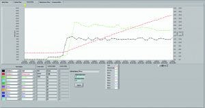
Photo 3: Ability to real-time trend all process values and quickly export trends
It should control five independent TFF trains, monitoring and recording process parameters from each one (Photo 3). It should enable “walk-away automation,” automatically stopping a TFF train when a set UF–DF goal is reached. We needed flexibility for processing volumes and high-precision diaphragm pumps to minimize shear stress on proteins. Operating pressure should extend up to 40 psi and flow rate range 1.0–100 mL/min. A simple graphical user interface (GUI) and user-friendly data retrieval and manipulation would facilitate operator efficiencies, as would real-time trending of process values. And the system would need a small footprint to minimize operational cost by making the most efficient use of laboratory bench space.
A User–Supplier Collaboration: BMS and PendoTECH had a history of about eight years working closely together in a customer–supplier relationship involving both new and existing products, so we had an established working relationship with key personnel in place. As required for a successful collaboration, we first established timelines and milestones, defining and aligning our strategic interests. Device development began with a feasibility evaluation to develop a system that must meet at minimum these key features: work with small volumes of product and use both existing and new smaller area filters in development; be fully automated and able to perform parallel processing in a small footprint; and include safety alarms and check parameters. All product development programs involve risks and unknowns. So we scheduled technical reviews and decision points throughout our program for project refinements and deciding next steps based on information gained.
Feasibility evaluations were performed to investigate key technical aspects of the project. One of those was whether PendoTECH’s microcontroller platform could handle the complex processing required to keep a TFF process running without errors at the speeds required. At the heart of many of the company’s electronic products is a microcontroller platform and associated expertise for programming complex tasks in the “C” language. Process-control systems often are defined partly by the number of inputs and outputs they can handle. For this system, each station has 11 inputs/outputs (I/Os), and a multistation multiplies that by five for 55, with two data ports to communicate with a GUI) running on a personal computer, thus yielding a total of 57 I/Os. The Freescale Semiconductor (now part of NXP Semiconductors) microcontroller at the heart of PendoTECH’s platform has been proven in many critical control applications such as factory monitoring systems and automobiles. Thus, selecting this control platform takes advantage of an I/O-rich architecture supported by a fast microcontroller processor, all in an industrial and compact form. A multitasking real-time operating system programmed in native “C” language provides the necessary flexibility to code complex and robust control algorithms for concurrently supporting five independent TFF processes. Even though the popular programmable logic controller (PLC) is used for many industrial control projects and has an advantage of nearly unlimited I/O capabilities, the microcontroller’s ideal features in factors of size, cost, and programming flexibility made it the superior choice for this project.
After feasibility testing of the microcontroller platform was successful, the project could move into its next phase. Microcontroller programming was completed and the control hardware configured. We tested a crude breadboard set-up with one station connected to observe its control performance — the other four stations had their processing running with no equipment interfaced. That testing was successful, so the formal user requirements could be defined (as listed in the “User-Requirement Specifications” box).
User-Requirement Specifications |
|---|
Five to 10 parallel tangential-flow filtration (TFF) process stations |
3 ft2 of bench space for five stations |
Use of level sensors for diafiltration/concentration points on main retentate vessel (versus a scale) so the level can be precisely controlled on a range of vessel volumes without concern for sensitivity issues and to remove space requirement for a scale. Vessel options of either 125 mL, 500 mL, or 1 L were selected for the product design space. |
Filtrate scale load cell with 0.01-g resolution and ≤1,000 g, with an option to increase up to 3,000 g with 0.1-g resolution to estimate filtrate flow/flux accurately by the change in weight over time |
Integration of automated throttle valve for transmembrane pressure control |
Simultaneous concentration and diafiltration |
Multiprocess recipe options for |
The project was budgeted and resources committed to finish system building, and it was decided for multiple reasons to limit the system to five stations at least initially. Further requirements were added to the detailed design:
To meet the challenge of fitting in 3 ft2 of bench space, a vertical design layout was required for each station.
To eliminate the need for a diafiltration pump, gravity feed with a valve would be the ideal approach.
Technical points included confirming the number and type of I/Os required, using a flow restrictor to control diafiltration feed without a pump, having two feed bags for fed batch operation, designing the GUI and load cells, liquid-level sensors, and interfacing with different vessels.
Performance of Key Components
Programming and Software Development: After software and GUI development and shakedown/debugging were completed (Photo 2),system use could begin. PendoTECH implemented changes and/or corrections based on feedback provided by BMS after initial use.
Microcontroller: With fine-tuning of the final programming, the microcontroller was highly efficient for reading inputs, sending outputs, monitoring alarms, and controlling recipe steps.
Pumps: For high-pressure capability, low-flow design, and a low-pulsation pump stroke, the final pump selected for use with this system was KNF Neuberger’s SIMDOS10 diaphragm pump. Because only a console model was available, PendoTECH worked with KNF engineering staff to develop an original-equipment manufacturer (OEM) panel-mounted model for use with the system that would fit within the compact-form design constraint.
Diaphragm pumps have check valves that control pump-chamber inlet and outlet flow during their pump strokes. It is important that those check valves seal during each pump stroke because performance can degrade with a drop in flow rate from the actual set point. To prevent particulates or foreign matter from interfering with check-valve sealing, the pump inlet tubes are outfitted with a 35-μm filter that can be replaced periodically. Even though that is the standard pump option, a modular design with pump controls and power delivered to the pumps from the base of the system enables easy integration of other pumps (e.g., peristaltic) for lower pressure processes.
Throttle Valve: UF–DF typically operates with one of three control strategies: constant retentate pressure, constant transmembrane pressure, or constant filtrate flux. A throttle valve controls TMP and retentate pressure to a user-entered set point. This is a key independent variable for process design and replaces a manual pinch clamp.
The throttle valve enables automation. As process conditions change, such as increased product viscosity during concentration, the valve can adjust automatically to control TMP. This prevents process upsets or alarms and enables processes to run automatically at the higher concentrations desired for many modern final formulations.
Another key feature of this throttle valve is that it prevents users from struggling to set it manually in the correct position that will meet desired pressure set points. With a 0.125-in. (3.2-mm) inner diameter (size 16) targeted for use with this TFF system, the travel distance for a valve to affect flow is about 20% of the tube diameter (~0.64 mm). The valve has a very complex “stepper motor” that can move in very small increments and thus enable precise control to user-entered set points. The valve runs an autocalibration procedure when the system is turned on to reset the home position of its motor positioner.
Load Cells for Permeate Weight: Load-cell performance is critical for measurement of permeate weight, which is used to estimate flow and measure diafiltration volumes. A basic industrial load cell was outfitted to a compact platform that minimizes bench space and cost. This load cell is connected to the system and tared to zero as needed through the GUI. In addition, a simple calibration wizard can be executed by users at any time based on a 500-g weight. That ensures accuracy of data collected during the experiments that follow.
System Design, Hardware Expandability, and Future Enhancements: There is large convergence of technology on this TFF system: solenoid valves, ultrasonic air detectors, capacitance-level sensors, a Wheatstone bridge load cell, compact Luer pressure sensors, a miniature diaphragm pump, and a valve with stepper-motor control. One objective in the system design was to minimize the amount of external wiring required. With so many external components required to control and monitor TFF processes, either panel-mount receptacles or wires running through water-tight grommets would be placed as close as possible to their point of use to streamline the length and organization of external cabling. Future enhancements should include addition of a possible on-line means of conductivity measurement and a low-flow flowmeter (0.1–15 mL/min) to enable permeate recycling with flow measurement for flux excursions. Photo 1 shows the final hardware design and a representative real time trends of the UFDF process parameters.
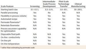
Table 4: Comparing UF–DF system capabilities at different scales
Performance of the TFF Screening System
Over the past two years, many scientists and engineers in BMS’s early phase purification development group have used this system extensively. As complex as the system is, its GUI has been described as easy to use. Mechanically, the level sensors are easy to adjust on their slide bars to desired concentration points. During this time, the five-station TFF screening system has demonstrated robust reproducibility. For three different BMS molecules, we have conducted 70 UF–DF runs in fed-batch mode, 45 concentrations to 60–75 g/L, and 45 concentration/diafiltration studies over a period of 45–50 days without any technical errors or loss of information. All 160 runs yielded complete recovery of all process material. The system was cleaned in place and sanitized with 0.2-N sodium hydroxide after each run. UF–DF studies were performed with maximum inlet feed pressure of 25 psi and maximum feed flow rate of 480 L/m/h. Tubing and the inline 35-μm filter were replaced with each change of molecule, and the permeate scale calibration was confirmed every 10 runs. The throttle-valve’s home position sensor was calibrated while replacing the system tubing according to its auto-calibration procedure.
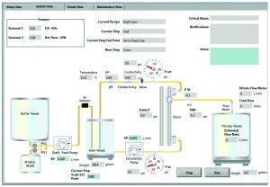
Photo 4: Intuitive GUI for process/pilot development system for scale-up
Scale-Up to Platform, Pilot, and Manufacturing
Table 4 compares typical UF–DF system capabilities. The multistation UF–DF screening system has shown excellent process scalability to intermediate and pilot scale. The UF–DF process parameters obtained from the multistation TFF system were scaled up successfully to a bench-scale operation with a membrane of 0.1–0.5 m2. The larger scale TFF skid used a PSG Quattroflow Q150 diaphragm pump that can operate ≤3 L/min for bench-scale operation, and a larger model can be used for process operations ≤99 L/min. A PendoTECH TFF process-control system that has been on the market for years operates only one independent UF/DF process at a time (Figure 1, a cart version of this system; Photo 4, the system GUI). It offers the same automation and control features as the screening system while adding features such as on-line pH, conductivity, and temperature sensing; retentate flow-control capability; options for on-line UV monitoring; and pump and process-scale flexibility.
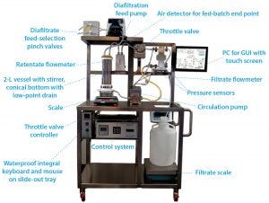
Figure 1: Process development system in cart for robust process development
With a new feature added to the TFF process control system, a robust design of experiments (DoE) can be conducted. To determine optimal flux and operational conditions, the GUI’s Process Excursion tab allows users to enter up to 10 different process conditions for feed flow and TMP. That can be set for up to four different concentrations, thus fully automating a matrix of 40 different process conditions. That allows for executing a range of UF–DF process conditions required to perform statistical DoE in a relatively short time. Each stage in Photo 5 would take place with the system in 100% recycle mode, with permeate redirected back to the retentate vessel and creating a roughly steady-state condition.
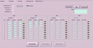
Photo 5: Process development system — excursions of ≤40 conditions in flow, transmembrane pressure (TMP), and concentration
A Pivotal Advancement
The multistation UF–DF tool developed through collaboration between BMS and PendoTECH is being used extensively by the BMS biologics process development team. The system has been pivotal particularly in accelerating early phase UF–DF process development and characterization activities. The capability to execute a completely automated statistical DoE study with minimal manual intervention is a first on the bioprocessing market (Photo 5). As new biopharmaceutical products work their way through the development pipeline, such novel process development tools will enable this industry to meet its goals of speed, flexibility, quality, and cost as laid out by the BioPhorum Operations Group (BPOG) in a number of publications (6–8).
Acknowledgments
We acknowledge Gregory Barker, Sibylle Herzer, and Matthew Conover of BMS for their contributions during this work. We also acknowledge John Benson (product design engineer) and Richard Holowczak (microcontroller programmer and integration expert) at PendoTECH for their technical contributions. This article is exclusively sponsored by PendoTECH.
References
1 Liu HF, et al. Recovery and Purification Process Development for Monoclonal Antibody Production. MAbs 2(5) 2010: 480–499.
2 Clincke M-F, et al. Very High Density of CHO Cells in Perfusion by ATF or TFF in WAVE Bioreactor™, Part 1: Effect of the Cell Density on the Process. Biotechnol. Progr. 29(3) 2013: 754–767.
3 Pollock J, et al. Integrated Continuous Bioprocessing: Economic, Operational, and Environmental Feasibility for Clinical and Commercial Antibody Manufacture. Biotechnol. Progr. 33(4) 2017: 854–866.
4 Raghunath B, et al. Best Practices for Optimization and Scale-Up of Microfiltration TFF Processes. Bioprocessing J. 11(1) 2012: 30–40.
5 van Reis R, et al. Linear Scale Ultrafiltration. Biotechnol. Bioeng. 55(5) 2000: 737–746.
6 Ebner CG. Facilities of the Future Conference: Innovating the Future of Manufacturing. Facilities of the Future Conference: Innovating the Future of
Manufacturing. ISPE 20–22 February 2018, Bethesda, MD.
7 Jones S. BioPhorum Operations Group Technology Roadmapping, Part 4: Efficiency, Modularity, and Flexibility As Hallmarks for Future Key Technologies. BioProcess Int. 15(2) 2017: 14–19.
8 Aeby T, Munk M. Meeting the Demand for a New Generation of Flexible and Agile Manufacturing Facilities: An Engineering Challenge. BioProcess Int. 13(11) 2015: S16–S23.
Corresponding author Atul Bhangale is a scientist II, Yan Chen is an associate director, and Anurag Khetan is site director of biologics process development at Bristol Myers Squibb in Hopewell NJ; 1-609-818-7205; [email protected]. James Furey is general manager of PendoTECH LLC.
You May Also Like
