Subscribe to receive our monthly print or digital publication
Join our 70,000+ readers. And yes, it's completely free.

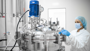
Figure 1: Clean-in-place (CIP) skid shared among multiple CIP clients; a shared CIP skid is shown with typical CIP clients of a monoclonal antibody process.
Risk of viral contamination is a an accepted part of developing biopharmaceutical products derived from mammalian-cell culture. Viral safety is achieved through a combination of complementary approaches such as selecting non–animal-derived raw materials, testing cell banks, testing for adventitious virus contamination during cultivation, and demonstrating viral reduction capacity of a purification process (1). The latter commonly is referred to as viral clearance by orthogonal purification.
Clearly, viral clearance and appropriate viral segregation are important considerations in biopharmaceutical manufacturing process and facility design. Good manufacturing practice (GMP) guidelines from the US Food and Drug Administration (FDA) and European Medicines Agency (EMA) emphasize that appropriate segregation of process operations is a regulatory expectation. For example, excerpts from the Pharmaceutical Inspection Convention Scheme (PIC/S) 2018 Guide to Good Manufacturing Practice for Medicinal Products, Part II provide the following guidance:
5.15 Closed or contained equipment should be used whenever appropriate. Where open equipment is used, or equipment is opened, appropriate precautions should be taken to minimize the risk of contamination.
5.22 Equipment and utensils should be cleaned, stored, and, where appropriate, sanitized or sterilized to prevent contamination or carry-over of a material that would alter the quality of the intermediate or API [active pharmaceutical ingredient] beyond the official or other established specifications.
5.24 Nondedicated equipment should be cleaned between production of different materials to prevent cross-contamination.
18.52 Appropriate precautions should be taken to prevent potential viral contamination from previral to postviral removal/inactivation steps. Therefore, open processing should be performed in areas that are separate from other processing activities and have separate air handling units.
The European Union EudraLex guidance document titled The Rules Governing Medicinal Products in the European Union, Volume 4: Good Manufacturing Practice (2) states the following:
5.18 Adequate cleaning and storage of the equipment is essential in order to avoid the risk of contamination for the products. Whenever possible, single-use cleaning materials should be used. The cleaning/decontamination procedures applied to multiuse equipment coming into contact with the product should be validated as explained in Section 10.2.
9.35 Measures to prevent cross-contamination appropriate to the risks identified should be put in place. Measures that can be considered to prevent cross-contamination include, among others: . . . (vi) Adequate cleaning procedures. The cleaning procedure (technique, number of sanitation steps, etc.) should be adapted to the specific characteristics of the product and of the manufacturing process. A risk-assessment should be used to determine the cleaning/decontamination procedures that are necessary, including the frequency thereof. As a minimum, there should be appropriate cleaning/decontamination between each batch. The cleaning/decontamination procedures should be validated as explained in Section 10.2.49.
The term appropriate is used repeatedly in the guidelines cited above. Some guidelines point to segregation of manufacturing areas — including heating, ventilation, and air conditioning (HVAC) supply — and others point to closed processing. The term appropriate is subject to interpretation. The above-referenced regulatory guidelines emphasize the high priority of product protection, preventing mix-ups as well as process crossover and carryover.
Process unit operations can be segregated using multiple approaches. One example is physical segregation, for which unit operations are housed in dedicated suites, or a bioprocessing system is isolated from potential contaminants in the environment. Bioprocessing systems can be isolated using single-use or functionally closed systems, with defined and validated cleaning and sanitization operations used to mitigate risks of environmental contamination.
Drug manufacturers often share equipment across multiple stations to streamline production and improve facility use. This includes the equipment used for cleaning and sanitization operations of manufacturing systems. Biomanufacturers will use extreme measures to segregate a post-nanofiltration operation from a cell-culture operation. However, they use a common glass washer or clean-in-place (CIP) skid for cleaning and sanitizing components from those two operations. Herein, we assess this apparent contradiction by using a mathematical model to evaluate the potential carryover/crossover risk.

Table 1: Process steps for model
Background
The potential carryover of a viral load can be modeled mathematically. Modeling can be used to determine quantitatively the sensitivity of a given purification step (or series of steps) to carryover contamination (3).
Carryover contamination can originate from different sources. Examples include
reuse of improperly cleaned vessels or transfer lines
sharing of instrumentation in multiple processing steps
aerosolization
operator carryover.
By determining the level of potential carryover, you can calculate the potential impact of sharing resources on multiple bioprocessing steps, then subsequently define appropriate risk-mitigation measures.
Viral clearance strategies of typical bioprocesses based on mammalian-cell culture are in the 15–18 log range (theoretical). Kærsgaard, et al. (3) determined that the critical potential carryover (CPCo) that could compromise viral clearance for an entire purification process is CPCo = Vbefore/RFlab, in which Vbefore is the volume before clearance takes place (harvest volume), and RFlab is the cumulative reduction determined by laboratory experiments. As Kærsgaard demonstrated, even extremely small carryover volumes (µL) could be critical. “Appropriate risk-mitigation measures” need to prevent transfer of such small volumes effectively.
Below, we use Kærsgaard’s mathematical model to analyze a theoretical situation in which a shared CIP system is used for cleaning both upstream and downstream bioprocessing equipment. Our analysis demonstrates how a systematic and science-driven model of viral segregation can be performed and how appropriate risk-mitigation measures can be defined.
For our model, we used a bioprocess system with a retrovirus-like particle (RVLP) contamination of 1010 RVLP/mL in the process stream. This extreme level of RVLPs (4) is used as a starting point to define a worst-case scenario, but the same principles could be used for other contamination conditions.
Case Study Model
Our evaluation uses a typical 2,000-L monoclonal antibody (MAb)manufacturing process with traditional multiuse equipment. Table 1 lists the purification process steps with corresponding theoretical log-reduction values. The purification steps represent a typical orthogonal approach with a cumulative viral clearance of 18 log.
Using Kærsgaard’s model, the theoretical potential carryover from harvest material to the UF/DF step is 2 × 10–15 L (2 fL = 2 × 10⁻³ pL). Carryover is calculated by assuming a culture volume of 2,000 L and dividing by 1018 to get the 18-log reduction in volume: 2,000 L / 1018 = 2 × 10–15 L.
Expression of carryover in terms of RVLP is calculated by converting volume to mL and multiplying by the number of RVLPs per mL (1010 RVLP/mL): (2 × 10–15 L × 103 mL/L × 1010 RVLP/mL) = 2 × 10⁻² RVLP.
In essence, a concentration of 1 × 10¹² RVLP/mL in a culture harvest could constitute a theorectical risk of carryover virus in the final product with an 18-log virus reduction scheme. That puts high demands on process execution to effectively rule out the risk of carryover. Insufficient cleaning and sanitization of multiuse equipment is a potential source of viral carryover. Another potential risk is the sharing of CIP systems for cleaning equipment used pre- and postviral clearance steps. Our focus is on the strategy of using shared resources for CIP operations. Mass-balance calculations are a measure of the extent to which the flushing and diluting of bioprocessing equipment affect potential RVLP carryover.
Figure 1 shows a CIP system process flow diagram (PFD) in which a single CIP system is shared among different CIP clients. Our model includes a single-tank CIP system. All formulated and tempered cleaning solutions (including ambient water rinses) initially are prepared in the CIP tank. Only hot-water rinses do not originate from the CIP tank and are supplied from a hot water-for-injection (WFI) distribution system. Based on the typical viral clearance strategy listed in Table 1, the highest risk scenario for RVLP carryover is one in which the constituents of a harvest vessel contaminate the final purification step represented by ultrafiltration equipment. Therefore, cleaning the ultrafiltration skid immediately after the CIP of an initial harvest vessel intuitively constitutes the highest risk of carryover from a shared CIP system. The 2,000-L harvest volume at the beginning of a purification process contains the highest potential RVLP load. This theoretical RVLP load must be removed fully before the ultrafiltration step to ensure a safe product.

Table 2: System volumes and flow rates; TFF = tangential-flow filtration
Table 2 lists system capacities used in our model. We used a working-volume to total-volume of 80% for all systems. Postdrain hold-up volume represents the volume in the tank remaining after draining (without air blowdown) in an ASME-BPE conforming system. We used a conservative assumption for the average depth of liquid-surface coverage of 1 mm and cylinders (L/D ratio = 2) to estimate tank surface areas.
Active flush hold-up volume is the hold-up volume in the tank during active CIP in a well-designed CIP system. For this model, we estimated the active flush hold-up volume to be the sum (2% of total tank volume) + (postdrain hold-up volume).
Line volume is the piping volume in the CIP circulation loop. We assumed full capacity of two-inch piping for this volume. The model assumed a 25-ft length of pipe for the supply and return lines for the bioreactor (total length = 50 ft) and 50-ft length for the corresponding lines on the tangential-flow filtration (TFF) CIP loop (100-ft total). Line postdrain hold-up volume corresponds to the volume in the CIP circulation piping remaining after draining (without air blowdown) in an ASME-BPE conforming system.
For our model, we start with an empty bioreactor that is soiled with spent media containing RVLPs. The model assumes a 10-L postdrain hold-up volume (includes a pool at the tank base and residual liquid adhering to tank sides, in pipework and other components) with an RVLP concentration of 1010 RVLP/mL. This amounts to a total of 1010 RVLP/mL × 10,000 mL = 1014 RVLP.
Consistent with a typical CIP recipe, the bioreactor initially is flushed with ambient water for four minutes. Initial rinse is a once-through flushing directly to drain with no return of solvents to the CIP skid. During flushing, initial concentration of RVLPs in the active flush hold-up volume after the first 61 L of water is introduced to the tank is 1014 RVLP/61 L = 1.6 × 10¹²/L (calculated concentration of 1.6 × 10¹²/L).
At the ASME BPE recommended flow rate of 140 LPM, four minutes represents 560 L of flushing volume, corresponding to about (560 L– 61 L)/61 L = 8.2-fold dilution of the RVLP concentration. For each hold-up volume, RVLP concentration will be reduced by a factor of e (base of natural logarithm; equals 2.718), which is ideal — assuming instant mixing and constant volume. Within the context here, we use a more conservative factor of two to compensate for nonideal flushing conditions. Therefore, flushing with a volume representing eight times the active flush hold-up volume dilutes the concentration of RVLP by a factor of 0.58 or 1.6 × 1012 × 0.58 = 6.2 × 10⁹ RVLP/L. Following the rinse, the system is drained, resulting in a postdrain hold-up volume of 11 L, containing 6.8 × 10¹⁰ RVLPs.

Figure 2: CIP tank and bioreactor recirculation: 650 L of caustic solution is charged into the tank and recirculated through the heat exchanger, to the bioreactor, and back to the CIP tank as indicated by the yellow flow path. During this process, any residual RVLP in the bioreactor will be mixed with the caustic solution. SB indicates sprayball location and Min. Distance indicates minimum distance between the process drain/recirculation valve manifold and the tank nozzle.
Following the initial rinse, the bioreactor is washed with a formulated, hot, caustic CIP solution and tempered in the CIP tank. As Figure 2 shows, the solution is supplied to the bioreactor, and spent CIP solution is returned to the CIP tank. During this wash-phase recirculation, temperature, flow, concentration, and time criteria (TACT principle) are controlled and monitored. During this recirculation step, the caustic solution is mixed with the latent RVLPs. By recirculating the caustic wash, the latent RVLPs cause CIP skid contamination, which could carryover to all clients of the CIP system.
For a 2,000-L bioreactor, we assumed a CIP supply of 140 LPM within this model. Based on that flow rate and a recirculated CIP wash strategy, we assumed a 650-L total formulated caustic volume to ensure efficient CIP function. Based on a total formulated caustic volume of 650 L + 11-L postdrain hold-up volume in the bioreactor, the concentration of RVLPs in the caustic is 6.8 × 10¹⁰ RVLP / (650 + 11) L = 1.0 × 10⁸ RVLP/L.
Unless the CIP skid is steamed in place (SIP), risk of residual RVLP in the CIP skid needs to be assessed. Assuming no blowdown of the CIP tank following caustic wash, a 6-L postdrain hold-up volume containing 1.0 × 10⁸ RVLP/L × 6 L = 6.0 × 10⁸ could be remaining in the CIP system before refilling the CIP tank with rinse water. Assuming a 650-L charge of rinse water in the CIP tank to supply the required 420 L of rinse to the bioreactor, the potential RLVP concentration in the rinse could be as high as 6.0 × 10⁸ RVLP/650 L = 9.2 × 10⁵ RVLP/L. Potential RVLP load in the postdrain hold-up volume (11 L) is 1.0 × 10⁷ RVLPs, which could contaminate the next client cleaned by the CIP system.
Incorporating two air blowdowns after the caustic wash and postcaustic water rinse of the bioreactor reduces postdrain hold-up volume to <0.5 L. That volume reduction decreases the potential RVLP load in the CIP system after the caustic wash to 1.0 × 10⁸ RVLP/L × 0.5 L/650 L × 0.5 = 3.9 × 10⁴ RVLPs. According to the model, those two blowdowns result in a more than two-log reduction (1.0 × 10⁷ RVLP compared with 3.9 × 10⁴ RVLP) into the next CIP client. When calculating the carryover into the TFF system in our model, the CIP system is blown down after both the caustic wash and the postcaustic rinse of the bioreactor.

Figure 3: Flush of tangential-flow filtration (TFF) tank; after cleaning of the bioreactor the TFF is flushed with water from the CIP tank, and any residual RVLPs remaining in the CIP tank after the bioreactor CIP is transferred to the TFF tank as indicated by the yellow flowpath. SB indicates sprayball location, and Min. Distance indicates minimum distance between the process drain/recirculation valve manifold and the tank nozzle.
The TFF skid in our example is cleaned immediately after the bioreactor (Figure 3). For the TFF system, we assumed an ASME BPE recommended flow rate of 85 LPM. CIP skid initially is loaded with 500 L of water to supply the 340 L required for a four-minute initial rinse of the TFF system. This rinse solution potentially contains a concentration of 3.9 × 10⁴ RVLP/500 L = 78 RVLP/L.
Following initial rinse, the TFF system is washed with a hot, caustic solution. The make up of this 500-L solution will dilute the RVLP concentration in the CIP tank as follows: (78 RVLP/L × 6 L)/500 L = 0.94 RVLP/L.
An air blowdown of the CIP and TFF systems follows wash recirculation. This step reduces the postdrain hold-up volume to <0.5 L in the CIP tank.
The addition of 500 L of water to the CIP tank for postwash rinse of the TFF tank reduces RVLP concentration in the CIP tank to (0.94 RVLP/L × 0.5 L)/500 L = 9.4 × 10⁻⁴ RVLP/L. That value corresponds to a theoretical total of 9.4 × 10⁻⁴ RVLP/L × 4L = 3.8 × 10⁻³ RVLP. This value is the amount remaining in the postdrain hold-up volume of the TFF tank after water rinse. A final hot-WFI rinse (originating from the WFI distribution system) of the TFF tank reduces carryover RVLP load further.
Our calculations of RVLP carryover from the bioreactor and through the CIP tank into the TFF module are based only on the dilution effect. We performed them using typical hold-up and flush volumes for this type of equipment and making a conservative assumption of the diluting effect of flushing (2.0 instead of 2.7 per hold-up volume).
Our calculations suggest that RVLP carryover could occur. However, risk of residual RVLPs remaining in the TFF system following a typical CIP recipe is mitigated. As we stated above, potential residual RVLPs in the CIP skid after cleaning the bioreactor is 3.9 × 10⁴ RVLP. Our model expresses a theoretical 5-log reduction of RVLPs per CIP process from dilution effects of CIP alone. In the worst-case scenario, RVLP load would be reduced by 5-log × 5-log = 10-log, which is better than the critical threshold value as calculated by Kærsgaard et al. (3). Sanitization from a hot caustic wash should reduce that RVLP concentration further. We anticipate a substantial effect (>2-log per CIP cycle) from the chemical and thermal sanitization. The combination of heat and high pH has a high antiviral effect against RVLPs and all other virus families (5–9).
Calculations such as those above must be interpreted with caution. They are valid only for systems that have no deadlegs, are well maintained, and have validated CIP operations. In addition, such CIP operations must be well monitored and controlled.
To Share or Not to Share
The model described here shows that a well-designed CIP system (conforming to the ASME-BPE standard) and operation can mitigate effectively the risk of carryover from a contaminated bioreactor to a subsequent client. A viral contamination >10-log RVLP/mL would be required for it to constitute even a remote risk. Such a high level of RVLP contamination would be considered an atypical event that would be easy to detect. That level also would trigger a formal decontamination of the bioreactor before starting a CIP process.
Development of proper CIP parameters to remove RVLP effectively includes considerations of drain hold-up volume, active flush hold-up volume, flushing volumes, and proper sequencing of washing and draining steps. Even if the example above reached a carryover well below the critical level defined initially, changing just a few CIP parameters could change the outcome drastically. The system considered is a medium-sized system. Systems servicing large skids will have longer piping runs and wider diameters, resulting in more potential for hold-up if the system is not designed according to ASME-BPE recommendations.
Once developed, CIP parameters must be monitored for unexpected changes that could occur between cycles. Finally, a plan to mitigate the risk of changes to a validated state is required. Operators must be trained on the proper procedures and techniques for removal, inspection, and installation of components (e.g., filter housings, flex hoses, and sprayballs) during normal operations to ensure that deadlegs are not created during equipment setup.
The risk of using a CIP system to clean different process equipment can be mitigated further by performing a “blank” CIP between CIP client targets. Thermal (SIP) or chemical sanitization (e.g., vaporized hydrogen peroxide, chlorine dioxide, Minncare sterilant) of a CIP skid between uses also would reduce or eliminate potential residual viruses. Even the implementation of a two-tank CIP system, in which rinse water is supplied to a CIP client from a CIP tank that is always once through can further reduce potential virus load during rinse phases. Those procedures can be validated to show removal of potential residual RVLPs in a CIP system following contamination by recirculating CIP fluids from contaminated CIP clients. After such risk-mitigation measures have been validated, a CIP system can be shared between process equipment with risks that are comparable with those of a facility using dedicated CIP systems.
Importance of Maintaining and Monitoring a Validated State
Time, temperature, and chemistry are relatively easy to monitor during CIP operation with in-line sensors, probes, and timers. Proper action and coverage are more difficult to achieve and maintain. An entire system — from CIP tank to a client, including lines connecting a system — must be designed according to ASME-BPE guidelines to ensure the absence of deadlegs in a system. A properly designed skid can be rendered uncleanable if a line is sloped or sized improperly, thus creating a deadleg where proper turbulent flow or air evacuation is impossible.
If a system is shared among CIP clients, precautions must be taken to ensure that a validated state is maintained. A system installed to meet ASME-BPE standard requirements may not achieve such requirements as the system is used. For example, elastomeric materials or other debris might be flushed through a system and be deposited in a sprayball, compromising coverage during CIP. That would result in “shadows” forming on portions of the tank that are not cleaned and flushed by a spray.
During daily use, changes to a system can cause deadlegs. Such changes to a validated state reduce effectiveness of CIP cleaning and clearance, ultimately increasing risk to patients. Actions that can be taken to reduce that risk include regularly inspecting sprayballs for debris and monitoring the time taken for systems to achieve their target conductivity and total organic carbon (TOC) levels. Once cleaning procedures have been defined, acceptable time durations to achieve sufficient conductivity and TOC limits in rinses should be validated.
If a system takes an unexpectedly long period to achieve a target conductivity or TOC value as an endpoint to a rinse step, chances are that the action (nonturbulent flow or in adequate coverage) is problematic during CIP. Such instances must be investigated and rectified immediately. Out-of-trend results indicate that a system is not cleaning adequately, and a failure mode and effect analysis (FMEA) approach should be used to evaluate the state of associated CIP procedures and systems. Ensuring overall virus safety by using multiple barriers concurrently is a sound principle to ensure robustness.
References
1 Harmonised Tripartite Guideline Q5A(R1): Viral Safety Evaluation of Biotechnology Products Derived from Cell Lines of Human or Animal Origin. ICH: Geneva, Switzerland, 1999.
2 Harmonised Tripartite Guideline Q7: Good Manufacturing Practice Guidance for Active Pharmaceutical Ingredients. ICH: Geneva, Switzerland, 2000.
3 Kærsgaard P, Kamstrup S, Halkjær E. Virus Segregation During Purification Processes: Calculation of Critical Potential Carryover of Virus. BioProcess Int. 16(9) 2018: 46–49.
4 Bolton G, Chen D. Proceedings of the 2017 Viral Clearance Symposium, Session 1.1: Upstream Mitigation, Part 1 — Cell Bank and Bulk Harvest Testing. PDA J. Pharm. Sci. Technol. 72(5) 2018: 455–460; doi:10.5731/pdajpst.2018.009092.
5 Boschetti N, et al. Stability of Minute Virus of Mice Against Temperature and Sodium Hydroxide. Biologicals 31(3) 2003: 181–185.
6 Use of Sodium Hydroxide for Cleaning and Sanitizing Chromatography Media and Systems. Application Note 18-1124-57 AE GE Healthcare: Uppsala, Sweden, 2006.
7 Borovec S, et al. Inactivation Kinetics of Model and Relevant Blood-Borne Viruses By Treatment with Sodium Hydroxide and Heat. Biologicals 26(3) 1998: 237–244.
8 Roberts PL, Lloyd D. Virus Inactivation By Protein Denaturants Used in Affinity Chromatography. Biologicals 35(4) 2007: 343–347.
9 Terpstra FG, et al. Resistance of Surface-Dried Virus to Common Disinfection Procedures. J. Hosp. Infect. 66(4) 2007: 332–338.
Robert Boulanger is a process specialist at CRB, Søren Kamstrup is biopharm QC microbiology specialist at Novo Nordisk, Marc Pelletier is a director at CRB, and Tim Corbidge ([email protected]) is a facilitator at BioPhorum. Jeff Odum (Sanofi), Buyoung Lee (Genentech), and Frank Radzai (Biogen) contributed to this article.
This document represents a consensus view, and as such it does not represent fully the internal policies of the contributing companies. Neither BioPhorum nor any of the contributing companies accept any liability to any person arising from their use of this document. The views and opinions contained herein are those of the individual authors and should not be attributed to the authors’ employers.
You May Also Like