Integrity of Single-Use Systems: Practical Applications and DeploymentIntegrity of Single-Use Systems: Practical Applications and Deployment
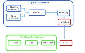
Figure 1: Product life cycle of single-use systems
Single-use (SU) technology plays an important role in modern vaccine and biologics manufacturing. System integrity, managed by critical process controls, ensures sterility and is a prerequisite for successful leak-free processing. Nonintegral systems cause loss of product, quality, and time; increase costs through investigations; and lead to potential safety problems. The BioProcess Systems Alliance (BPSA) issued a white paper in 2017, Design, Control, and Monitoring of Single-Use Systems for Integrity Assurance (1), that describes in detail the strategies for design and quality assurance with regard to system integrity within the single-use systems (SUS) life cycle (Figure 1). Several other publications address design and quality assurance for SUS from the broader perspective of system integrity (2–4).
The following four case studies focus on system-integrity challenges. The first example describes development of an improved pressure-decay test method for bioreactors. The second explores difficulties inherent in shipping liquids in SU bags. The third highlights the difficulties involved in developing a high-integrity SUS design. And the fourth discusses implementation of point-of-use leak testing in a final filling application. We direct readers to the BPSA white paper, the references provided there, and the references herein for a fuller discussion of SUS integrity assurance.
Detecting Gross Leaks
All steps of a biologics manufacturing process require careful handling to prevent product loss and damage. Any risk or hazard can be costly for a manufacturer, potentially reducing the effectiveness of a product or resulting in having to discard a product altogether. End users increasingly are requiring nondestructive integrity testing by manufacturers of SU bioreactor bags to ensure the overall quality of a final SU bioreactor assembly.
Using a Semiautomatic Pressure-Decay Leak Tester: In our first example, a customer with a SUS comprising multiple small-volume bioreactors required a nondestructive integrity test on each chamber before assembly. Initially, the customer developed and implemented a manual pressure-decay test at the manufacturing site. Each bioreactor was pressurized at 2 psi (0.14 bar), unrestrained, and monitored by an operator. That process proved to be time consuming, however, and lacked sensitivity and repeatability. The bag manufacturer developed a semiautomated, nondestructive restrained pressure-decay test method as a solution. These variables were used to establish the process parameters:
test article volume
materials of construction
test pressure
fill time
stabilization time
test time
allowable pressure loss (ΔP)
overpressurization.
Each bioreactor bag was designed with two rigid ports welded on either end of a long, thin, rectangular bag body. A hinged aluminum test fixture was designed to place the bag securely between restraining plates that closed shut to establish repeatable test volumes with limited expansion. A thin piece of rigid, porous material was machined and mated to the surface of the fixture so that potential leaks in the film would not be plugged. Besides limiting volume, a major advantage to using restraining plates is that we could test at high pressures without stressing the seals. For this particular SU bioreactor system, a pressure of 5 psi (0.35 bar) was established as safe during use, so it was selected as the new test pressure — an immediate improvement of 250% sensitivity over the previous method. Materials of construction in the bag assembly were assumed to be constant, so the remaining variables were used to determine the pressure-decay test parameters.
For a test cycle, an operator placed a bag into the fixture, closed the hinge, and started the automated process in which the leak testing unit hermetically sealed the two end ports for pressurization. Samples were overpressurized initially to minimize the viscoelastic nature of the material. That step briefly overfilled a bag to 120% of test pressure, which stretched the material and reduced turbulent flow in later steps. Then the bag was fully exhausted, followed by a brief pause before it was filled again to test pressure for a given time (fill time). The test article was isolated from the pressure source and allowed to approach equilibrium for some time (stabilization time). Pressure decay of that near-equilibrium state was recorded as a function of first and last data points over a given time (test time). That function/change/differential is ΔP.
To determine whether a bag was acceptable, a certain pressure loss over a set amount of time correlated with a particular leak rate. Leak rates can be identified by comparison with what is known as a leak standard: a metal orifice with a calibrated leak that can be added to a system. Notably, no global standards exist for a maximum acceptable hole size in sterile barrier systems, and leak-rate requirements currently are driven by customer feedback and industry trends. A pass-or-fail indicator based on the maximum allowable pressure decay for selected cycle times signals the outcome of the test, and failed samples can be subjected to as many as three retests.
To calculate the allowable pressure loss (ΔP) for selected cycle times, operators tested and retested a sample population of known nonleaking bags, with results verified through bubble emission, to create two data sets. Those sets were combined. The mean and standard deviation of the known good bags were used to determine an allowable pressure-loss limit representing the maximum natural pressure decay observed on nonleaking parts.
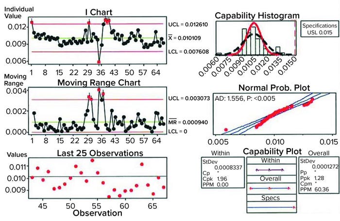
Figure 2: Sample data analysis for establishing process capability of pressure-decay parameters; shown here are results of analyses performed on previously untested, nonleaking bags.
An upper control limit (UCL) of 0.015 psi (1 mbar) was determined by the combined data (indirectly shown in Figure 2: Sample data analysis for establishing process capability of pressure-decay parameters; shown here are results of analyses performed on previously untested, nonleaking bags). With application of that UCL, calculating the process capability of the test method ultimately showed that a good bag could fail in one out of 1,000 tests. Then the limit was applied to known defective bags. Doing so showed that the pressure-decay values for gross defects far exceeded those of nonleaking samples, nearly always leading to a failure. Bags were validated for retesting up to three times to verify integrity, with the caveat of setting them aside for 15 minutes between tests so that temperature and viscoelastic effects could return to a steady state. Thus, the probability of misidentifying a pass or failure three times was highly unlikely. Only good bags representative of the natural variation in pressure decay as shown by the samples would be accepted.
The conclusions of the test method show that it is possible to identify a nonconforming part correctly, ensuring the integrity of a final SU bag nearly 100% of the time. Compared with the previous method (or its predecessor), the semiautomatic test method performed 55% faster and with greater repeatability (or reproducibility). It also detected gross defects that were less than half the size of those detected by the previous method. For anyone who wants to improve assurance of SUS product integrity, it is highly desirable to develop repeatable, deterministic test methodologies that catch potential failures rather than to use error-prone manual or qualitative methods.
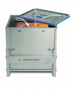
Flexsafe bag and shipping solutions (Photo Courtesy of Sartorius)
Shipping Liquid Products in Single-Use Systems
A second case study describes problems caused by inadequate consideration of SUS integrity during development of a liquid-buffer shipping process.
SUS integrity is relatively easy to manage when factors such as operator handling, support equipment, and process conditions are controlled. But when liquids are shipped in a SUS, users will lose control of those conditions. Containers are exposed to vibration, shock, and temperature changes during shipping. Packing and unpacking activities can damage container contents. In the past, shipping liquids in SU containers was handled case by case. Success in shipping depended on a cautious approach and, to some extent, luck. Fortunately, more options and procedures are now available to help users with liquid-filled shipment design (5).
A biotechnology company made and packaged a powdered, raw buffer mixture in SU bags. The bags were stored, then transported to another location of the same facility for use in a drug-substance purification process. The manufacturing and logistics process operated without incident.
The company decided to change from purchasing powdered raw materials to purchasing buffer solution in a ready-to-use liquid format. To keep things simple for the biomanufacturing operation, that solution was supplied in the same type of SU bags used in the company’s buffer-preparation facility. Because 200-L bags at that facility typically were handled in cylindrical drums, the chemical manufacturer was approved to use its own cylindrical drums as bag holders. But those drums had not been used previously as SU bag accessories.
Lack of understanding by the chemical manufacturer and lack of coordination with experienced SU engineers and logistics personnel led to handling and shipping of liquid-filled bags in drums that were not designed or tested for use with that type of shipment. As a result, bags were frequently damaged in transit, requiring manufacture of excess material to accommodate for shipping losses.
Because the bags were damaged during shipping, a process-improvement team concluded incorrectly that the bags were the problem and that changing them (supplier and/or material) would solve it. More detailed investigations were performed to reduce shipping losses, and those investigations revealed that no shipping validation following appropriate ISTA (6), ASTM (7), or other standards had been performed. There were no written procedures for preparing liquid-filled bags in drums for transportation, and the chemical manufacturer had limited experience with SU technology.
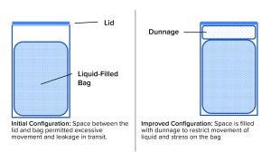
Figure 3: Adding dunnage improved reliability of a liquid-filled bag during shipping.
A bag change was made, and the biotechnology company insisted on a proper shipping-validation study as part of the change-control process. The chemical manufacturer agreed with that requirement, and the change-control work started with development of a pack-out procedure that provided specifications for the bags, drums, closures, and dunnage (packing material inside the drum). Figure 3 is a schematic diagram of the configuration before and after redesign. Now, detailed instructions on how to place bags in drums, fill them, disconnect them from the filling line, add dunnage, close the drums, and load them onto pallets are provided in batch documents and written procedures. The resulting shipping configuration (bag + liquid + drum + dunnage), packed and palletized according to the standard operating procedure (SOP), was tested using consensus industry standards. As a result, shipments can be made without significant losses and without stress for the supplier and customer.
It is highly recommended that anyone who intends to ship liquid-filled bags take the time to design and validate shipping systems for their proposed use. Systems designed and built for liquid shipping in bags are commercially available (Figure 4). BPSA published a white paper in 2021 that addresses transit testing for biopharmaceutical manufacturers and their suppliers (8).
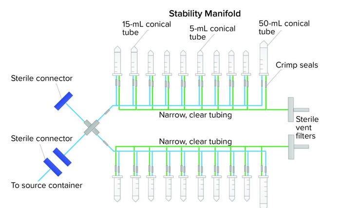
Figure 4: Closed, single-use stability-sampling manifold
Difficulties of an Integral Single-Use Assembly Design
SU assembly manufacturers and end users both want the same outcomes for new SU assemblies — one outcome of which is an integral system. Getting there, however, can be a painful experience for all parties. A third case study describes how we went from a preliminary to final design that showed leaks along the way. The assembly was a sampling manifold with 5-mL, 15-mL, and 50-mL conical centrifuge tubes with caps (Figure 4). The manifold had small, custom-made ports connected to narrow tubing on a main process line. The purpose of the assembly was to transfer small-volume stability samples (down to 2 mL) from a bulk-product vaccine container. The goal was to keep the sampling process closed and sterile using thermoplastic elastic tubing and sterile connectors to the bulk container. Although the system was used under atmospheric pressure conditions, the physics of an assembly with 20 little caps and port connections easily could allow for potential leaks when a manifold is filled with liquids, so vigilance regarding integrity during the project was necessary.
Figure 5 shows a high-level flow of the design and testing phases. The preliminary design was reasonable; it specified 100% integrity testing of each assembly lot by the assembly manufacturer. This requirement was placed on the drawing. That manufacturer tested the first prototype’s integrity by immersing it under water for five hours. No leaks were detected. Next, the end user tested the same manifold by water immersion, but for a shorter time and while the assembly was filled with nitrogen gas at 2, 5, and 15 psi (0.13, 0.33, and 1.03 bar, respectively). Water immersion was selected over other methods because it could be implemented rapidly as a quick check, and both parties could execute an integrity test using that method. Under all pressure conditions, bubbles were found around a few of the cap areas. A torque measurement range was added to the design drawing for each size of the threaded caps so that they are tightened accordingly during assembly. Those measurements were specific to the cap size and cap type. In addition, a narrow silicone gasket was added between the threaded cap fitting and the conical container to ensure that the seal interface was not hard plastic on hard plastic. Finally, the assembly manufacturer’s test protocol was updated to match the user’s test method more closely because the user could detect leaks that the supplier could not. Because 15 PSI (1.03 bar) was too high for the system of small tubes and caps, that test pressure was omitted from all future testing. It had been used only to challenge the system.

Figure 5: Design and integrity testing phases of a custom stability manifold
The second prototype was completed, tested, and sent to the end user. On receipt, several caps were visibly cracked. That was due possibly to the addition of the silicone gasket, which may have required a new torque range, or to cracks that formed after gamma irradiation — or a combination of both. Because the gasket might not have been suitable for the cap-and-container combination, the caps and fittings were custom-molded together to reduce the number of potential leak points. The design drawing was updated not only to specify 100% integrity testing before gamma irradiation, but also to require integrity testing on one unit per lot after gamma irradiation (Note: Although that integrity test was not technically destructive, that unit was not included in the lot shipment sent to the end user). The final design was completed, and the end user tested it for integrity by water immersion (a practical test for a small manifold such as this) and by using a newly purchased bag/assembly integrity-testing machine that could detect changes in pressure as pressure was applied slowly. Both tests passed on multiple units, and the design was considered completed and integral. The order could therefore be placed, and the system was implemented for current good manufacturing practice (CGMP) production.
All that work took 1.5 years to complete, but finally, the assembly systems for stability sampling now are well designed and tested to prevent product leaks. In this case, because the assembly manufacturer tests the product before and after gamma irradiation, a point-of-use integrity test is not performed, although that could be an option for similar designs. With “integral vigilance” by both the assembly manufacturer and end users, even complex, custom designs can be made leakproof. Methods will need to be adapted depending on design size and complexity.
Critical Assembly Point-of-Use Leak-Testing Application
As seen with the widespread adoption of SU assemblies in industry, their use provides many advantages, including speed of implementation and manufacturing site flexibility. In highly critical sterile applications, point-of-use leak testing of an assembly can help mitigate risk, freeing limited isolator space for more critical operations. In this fourth case study, an integrity test method was developed and validated for a SU redundant filter and tubing set used in final-fill operations.
A risk-based approach was used to identify the project scope:
identification of risks and parts of the assembly to test
identification of test risks and development to ensure robust analysis
validation of the test to prove that critical defects are found reliably, without risk of false failure.
Although assembly design and vendor controls substantially reduce chances of failure, some risk always will remain at a manufacturing site after installation. Therefore, critical portions of the assembly that presented risks were identified for testing (all assembly elements and connection points after the sterile filter). Waste bags and noncritical parts of the assembly were isolated from the test to focus on critical aspects and maximize test sensitivity within those sections of the assembly.
A number of test methods were considered, reviewing test sensitivities as well as manufacturing and space constraints. A tracer gas (helium) leak test was deemed unfeasible during operation, and although a custom (manual) pressure-decay test was considered, such a method would add time and complexity to the test development, its validation, and ongoing operation of a decay test by manufacturing. Thus, pressure decay using an automated integrity tester was chosen because it had the requisite defect resolution, provided a compact footprint, was easy to use, and had standard documentation for GMP manufacturing.
Test risks were reviewed thoroughly, their theoretical impacts were calculated, and factors were tested explicitly to ensure development of a final test that would be robust and reliable in manufacturing operations. Among those items reviewed for impact were
variations among assemblies
test-equipment calibration and equipment repeatability
environmental effects — temperature and heating, ventilation, and air conditioning (HVAC) reliability
technician setup of assembly and test equipment
test pressure
repeat testing of assemblies.
With firm knowledge gained from testing and feasibility work, formal development of the test was undertaken to finalize its process parameters, including stabilization and test times. With clear background and risk identification, test parameters were found quickly that maximized sensitivity and reliability with minimal manufacturing downtime.
Test Validation: A risk assessment was undertaken to drive the specifics of formal test-method validation. Commensurate with the risks noted, the following factors were included:
assembly lot variation(two assemblies from each of three assembly lots were used)
installation variability (three operators conducted testing)
environment (testing spanned three days)
potential defects (testing considered integral assemblies as well as assemblies containing a 25 µm defect).
Repeat testing was conducted to evaluate repeatability and reproducibility considering the above factors. Test validation was deemed to be successful with greater than eight standard deviations of separation between integral and defective assemblies.
With careful consideration, on-site integrity testing of critical assemblies can be implemented easily with off-the-shelf test equipment to achieve clear risk reduction. Careful, risk-based testing can maximize use of manufacturing space while maintaining low risk, even in highly critical operations.
Integrity-Testing Methods for Real-World SU Implementation
The importance of system integrity is well recognized, but tools and methods to monitor and ensure integrity only recently have become widely available. Experiences such as those described above and in other publications (9) help to illustrate the struggles — and triumphs — in real-world implementation of SU technology.
The biopharmaceutical industry continues to tackle challenges with SUS integrity assurance. BPSA’s system integrity committee is continuing activities extending from its work on the white paper (1), and members are supporting new efforts. Of particular note are two recent ASTM (www.astm.org) standards: E3244-20, Standard Practice for Integrity Assurance and Testing of Single-Use Systems and E3251-20, Standard Test Method for Microbial Ingress Testing on Single-Use Systems (4, 7). A BPSA guidance on transit testing for biopharmaceutical manufacturers and their suppliers also has been published recently (8).
Progress is being made, but more help is needed to address the challenges. Please contact us or BPSA (www.bpsalliance.org) for information about how to get involved.
References
1 Design, Control, and Monitoring of Single-Use Systems for Integrity Assurance. BioProcess Systems Alliance: Arlington, VA, 2017; http://bpsalliance.org/pdf-download-form-11.
2 Repetto R, et al. Technical Report 66: Application of Single-Use Systems in Pharmaceutical Manufacturing. Parenteral Drug Association: Bethesda, MD, 2014; https://store.pda.org/TableOfContents/TR66_TOC.pdf.
3 ISPE Good Practice Guide: Single-Use Technology. International Society for Pharmaceutical Engineering: North Bethesda, MD, 2018; https://ispe.org/publications/guidance-documents/good-practice-guide-single-use-technology#.
4 ASTM E3051-16. Standard Guide for Specification, Design, Verification, and Application of Single-Use Systems in Pharmaceutical and Biopharmaceutical Manufacturing. ASTM International: West Conshohocken, PA, 2016.
5 Shanley A. Best Practices for Shipping Single-Use Systems. Pharm. Tech. 42(5) 2018: 55–57, 61; https://www.pharmtech.com/view/best-practices-shipping-single-use-systems.
6 Guidelines for Selecting and Using ISTA Test Procedures and Projects. International Safe Transit Association: Lansing, MI, 2018; https://ista.org/docs/2018_ISTA_Guidelines.pdf.
7 ASTM D4169-14. Standard Practice for Performance Testing of Shipping Containers and Systems. ASTM International: West Conshohocken, PA, 2016.
8 Transit Testing Guidance for Single-Use Components and Assemblies. BioProcess Systems Alliance: Arlington, VA, 2021; https://bpsalliance.org/pdf-download-form-transit-testing.
9 Masy C, Bauer J-Y. Integrity Assurance for SUS: End-User Perspective. BioPharma Asia, 13 March 2019; https://biopharma-asia.com/magazine-articles/integrity-assurance-for-sus-end-user-perspective.
The authors are members of the BPSA systems integrity committee. Nicholas Batt is a development engineer at EMD Millipore; Jared Boggs is a new-product development engineer for Charter Medical; corresponding author Hélène Pora is vice president of technical communication and regulatory strategy at Pall Corporation, 3 rue des Gaudines, 78100 Saint Germain en Laye, France; [email protected]. Mark Petrich is a director at Merck & Co., Inc.; and Kirsten Strahlendorf is deputy director–principal scientist at Sanofi Pasteur.
You May Also Like
