- Sponsored Content
- Information Technology
Challenges and Benefits of Networking Process Control Manufacturing Systems: Integration to Business Systems in Industry 4.0Challenges and Benefits of Networking Process Control Manufacturing Systems: Integration to Business Systems in Industry 4.0
Sponsored by PendoTECH
Networking of manufacturing process control systems can lead to benefits of efficiency, increased productivity, and better facility use, leading to lower cost of goods (CoG). Furthermore, integration of manufacturing systems with manufacturing execution systems (MESs) upward to an enterprise resource planning (ERP) business system improves overall organizational efficiency. An ERP system enables optimization of intrafacility manufacturing resources. For multiple manufacturing facilities, it facilitates optimization across a company’s manufacturing network.
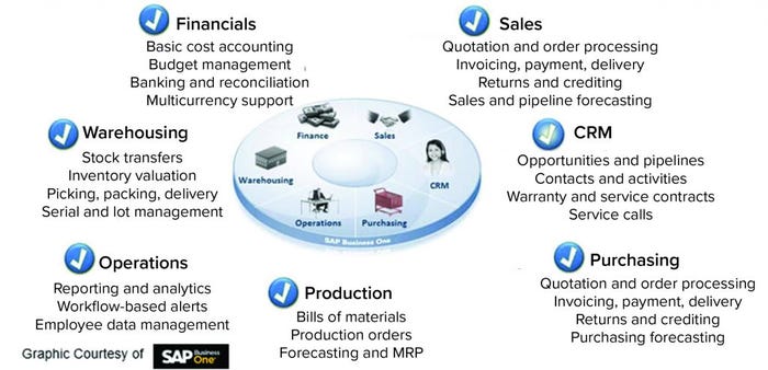
Figure 1: Enterprise resource planning (ERP) system and its functions (CRM = customer relationship management)
Enabling Technologies and Systems
At the enterprise resource planning level (Figure 1), a sales module can monitor incoming orders and forecasts of product demand. A financial module can track cost accounting and impact of fluctuating currencies to optimize profitability. A warehousing module can manage logistics and track available raw materials at different locations. It also can relay to the purchasing module where more raw materials are required and the amount needed, then generate required purchase orders.
In biopharmaceutical operations, production runs from cell inoculation to seed culture to drug substance can be lengthy processes (weeks to months). Managing company resources to optimize and maximize facility use is critical in terms of having the correct materials on hand at the right time to complete a production run and prevent costly bottlenecks. Manufacturing processes must comply with current good manufacturing practices (CGMPs), so quality management system (QMS) requirements are stringent for raw materials, processes, and final products.
Desired Devices |
|---|
Bioreactors, filtration skids, chromatography skids, centrifuges, pumps, scales, tubing pinch valves, flow meters, on-line analyzers/cytometers, individual sensors (e.g., for pressure, temperature, conductivity, absorbance, fluorescence, pH, turbidity, and OD), tubing welder, tubing sealer, air-in-tube sensors, level sensors, temperature control unit (TCU), custom robot, cell washing and harvest system, cryopreservation system, filling system, labeler, bar code reader, and sampling device |
The evolution of single-use technologies (SUTs) over the past decade to the forefront of biomanufacturing has increased facility flexibility. SUTs eliminate many cleaning and sterilization requirements and facilitate rapid facility turnover between production runs. However, with multiproduct facility capability comes increased complexity in supply chains for SUT components such as bioreactors, tube sets, and filtration assemblies, all of which are part of required raw materials to run processes.
With Industry 4.0 and Industrial Internet of Things (IIoT), companies can take advantage of strategic planning, strong visions, and technological advances to create a disruptive force for operating efficiently to meet customer demands. Industry 4.0 and IIoT enable connectivity between business systems and manufacturing systems to share data. At the manufacturing level, equipment and sensors monitor and control processes and collect data. Part of data collecting relates to learning a process in depth, including what variables or conditions of a process can affect process outcomes such as product quality attributes (PQAs). Such process analytics practice is evolving toward the use of artificial intelligence (AI) for making process adjustments to maintain parameters within certain boundaries and ensuring positive outcomes in production runs. Those adjustments could prevent failures (which can be costly in terms of lost raw materials) and could lessen the ability of a company to meet customer demand. An enterprise resource planning system can feed an MES system to initiate a production run comprising 10 or more unit operations (often in series) that must be orchestrated optimally over many weeks (Figure 2).
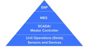
Figure 2: Process systems
Industry 4.0 can maximize the likelihood of production-run success by using process analytics to monitor and control such a process. With a supervisory control and data acquisition (SCADA) and a high-level control system that connects and communicates with different process unit operations, process monitoring and control can be conducted in the most efficient time frame. A SCADA is a computer system for gathering and analyzing real-time process data. A supervisory system sends commands to a process controller, which performs control actions. Using Industry 4.0 increases success rates and decreases process times, thus dramatically decreasing relative CoGs. Furthermore, networked connectivity of a control system with other systems such as a quality control (QC) laboratory information management system (LIMS) can be used to create electronic batch records and speed-up product release.
Part of strategic planning is to design and then validate a robust system that complies with CFR 21 Part 11 guidelines for electronic records and signatures. Good automated manufacturing practice (ISPE’s GAMP 5 Guide: A Risk-Based Approach to Compliant GxP Computerized Systems is the 5th edition) is accepted by the industry as the guideline to capture user requirements specifications (URS), create a functional design (FRS), and specify a detailed design specification (DDS) followed by the building of system architecture. Following GAMP methodology, that process is followed by the installation, operational, and performance qualifications (IQ/OQ/PQ) protocols to bring a facility online.
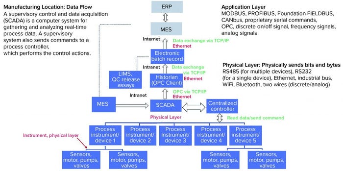
Figure 3: Manufacturing data flow
Communication and Connectivity Levels
For Industry 4.0 to be realized in manufacturing biologics such as vaccines, viral vectors, and allogeneic and autologous cell therapies, more coordination is needed between many parties. Major control-component suppliers, MES suppliers, historian providers, and sensor and device instrumentation manufacturers that handle products or process samples for measurement must coordinate their efforts with each other.
Two key concepts to keep in mind are communication and connectivity. At the SCADA/control system level, the control system, self-contained unit operations (often referred to as skids), sensors, and other devices must be connected and communicate in the same “language.” Connectivity often is defined by a physical layer, which consists of a hardware device that creates the physical connection between devices and must be common among devices for them to communicate (e.g., WiFi to WiFi).
Communication over a physical layer is the application layer. The same way people must use the same language to communicate, devices must speak the same language to communicate with each other. Use of digital data between devices rather than traditional analog methods allows much more information to be exchanged. For example, by contrast with analog devices, digital devices can send data pertaining to required maintenance or the remaining life of a UV-light–emitting diode (LED) on a detector in a chromatography system. Figure 3 shows a hypothetical manufacturing location data flow, including common application and physical layers.
From the SCADA upwards, the physical layer is typically Ethernet. The OPC application protocol is used to send data to historians such as the PI System historian from OSIsoft, which is commonly used in the industry. However, challenges exist with smooth integration of elements below the SCADA/control system to create a truly intelligent system. Historically, a few dominant control-system manufacturers based on geographical location have dominated the market based on their complexity, the large infrastructure that those manufacturers maintain, and the large investments made by both those manufacturers and (in-turn) end users to keep that technology up to date. In the digital world, many of those control systems are not standardized.
Legacy large-scale control systems were built around communication standards introduced decades ago, so they may be incompatible with one another. As processes evolve to increase automation, the ability to integrate multiple control systems is hampered by such incompatible communication standards.
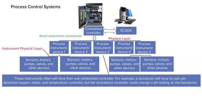
Figure 4: Centralized process control system with numerous unit operations
Interconnected Devices
Many devices can be used in a manufacturing site to facilitate an “intelligent” process, with the requirement that they be controlled remotely and data can be read from them (see “Desired Devices” box). For example, a SCADA system connected to a bioreactor can initiate that a culture sample be taken by an analytical instrument connected to an autosampler. The result of metabolite analysis is completed and reported to the SCADA, which in turn initiates appropriate actions to the bioreactor controller. Each of those actions (sampling, comparison, action) is recorded on a batch record associated with the production run. Additional important data would be the lot number and calibration record of the process sensors, which could be read digitally.
Figure 4 shows a centralized controller for both connectivity and communication, with both simple and complex systems. One problem that can arise is that a desired device might not have integration options — or if it does, that capability may not be compatible with the centralized controller. That is where the completed “intelligent plant” potential can be broken. Some devices do not even have a simple interface such as remote start-and-stop features.
The following are centralized controller generic methods used for talking to devices. Control systems often are defined by the number of inputs/outputs (I/O) in use.
Digital communication (e.g., MODBUS) capabilities can read and write parameters, send remote commands to change modes or settings, monitor alarms, capture device data for multiple purposes such as device issues, and send maintenance or other notifications.
Discrete on/off signal devices are similar to remote switches that can start an instrument (or device) such as a pump or open and close a valve. These devices also can read an alarm output.
Frequency signal devices can read or send digital values through a pulse reader or pulse generator (commonly used to transmit flow meter readings).
Analog signal (traditional A/D and D/A) converters send values in bits across a range that is set the same on both a transmitter and a receiver. For example, to transmit a temperature, both devices would be set from 0 to 100 °C. A converter uses two wires, and either a current (most common is 4–20 mA range) or voltage signal (0–10 V).
Precision is limited to “bit resolution” such as 8-bit to 16-bit, which “slices” the signal range to that many increments (8-bit is 28, which is 256 increments). Slight differences can occur in values between transmitters and receivers because of signal loss and slight hardware component variances.
Analog signal with HART is the same as the analog-signal device above, but it can send some basic digital information over copper wires transmitting analog signals.
Device Integration
Two things need to happen for integration of all devices to make intelligent manufacturing a reality. First, device developers must design required physical and application layers to make them connect and communicate. That requires more than a change in hardware interfaces. Device developers will need to design specifications for such instruments and relay them to software programmers of such instruments to implement software code and design instrument interfaces and menus as well as to hardware engineers to enable access to those features. With advanced planning, the costs of doing so will be marginal. After design of an instrument, addition of such features is nearly cost prohibitive without starting from scratch. Some instruments have universal applicability to many processes in many industries, so some manufacturers offer off-the-shelf options for a wide range of physical and application layers add-ons by circuit-board cards that can be inserted into a panel (e.g., some popular weighing scales).
Second, standardization among control system manufacturers must occur to make intelligent manufacturing a seamless process. That will allow end users to select the best devices for their processes and not exclude options simply because they do not speak the language of control systems being used. Emerging standards such as single-pair Ethernet, OPC-unified architecture (OPC UA), and time-sensitive networking (TSN) are evolving rapidly. Manufacturers that adopt such technologies at the heart of their control systems and devices in turn will help to accelerate the development of advanced biopharmaceutical processes.
Promising Steps Forward
Promising steps are being made toward the realization of Industry 4.0 in biomanufacturing: convergence of single-use manufacturing technologies, emerging standards coming on line for digital communications, and instrument device suppliers ensuring “smart” interfaces for remote operations. Proper strategic planning and vision will be required to create a fully automated, ideal facility of the future.
Richard Holowczak, PhD, is control system software manager at PendoTECH. Jim Furey is founder and general manager at PendoTECH, 1-609-799-2299; [email protected], www.pendotech.com.
You May Also Like


