Subscribe to receive our monthly print or digital publication
Join our 70,000+ readers. And yes, it's completely free.

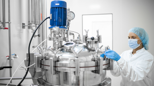
Figure 1: Examples of equipment used for low-pH viral inactivation; (top) a single-use bag system with an integrated mixer; (bottom) a typical stainless-steel tank displaying common appurtenances such as inlets, outlets, thermowells, and so on (photos from Sartorius and Feldmeier)
Viral clearance is a fundamental aspect of viral safety for biopharmaceutical products. Regulatory agencies around the world require biomanufacturers to segregate their operations appropriately to mitigate the risks of carryover contamination from previous process steps or product batches and of crossover contamination between product(s) made in the same facility. Guidelines are vague in defining “appropriate,” leaving biomanufacturers to interpret regulatory expectations and define their own virus reduction and segregation strategies. Given the differences among manufacturing processes and facilities housing such operations, it is unsurprising to see a range of segregation strategies adopted by different companies.
Herein we offer the second in a series of operational virus segregation strategies that could be considered when designing a biopharmaceutical facility. Appearing in BioProcess International’s April 2020 issue, the first installment of this series discussed the potential for cross-contamination from clean-in-place (CIP) systems that are used across a number of multiuse systems (1).
Monoclonal antibodies (MAbs) have proven to be valuable biopharmaceuticals for a number of diseases. These complex molecules are produced most often by recombinant mammalian cell lines such as Chinese hamster ovary (CHO) cells expressing the antibody of choice in culture. Many such cell lines express retrovirus-like particles (RVLPs). They are secreted into cultivation medium and considered to be process-related impurities.
Current regulatory guidelines require that RVLPs be removed from final, purified MAb products with the same efficacy as are infectious viruses (2). According to the ICH Q5A document, the requirement for virus clearance capacity is that an “entire purification process should be able to eliminate substantially more virus than is estimated to be present in a single-dose equivalent of unprocessed bulk” (2). The same guideline offers an example of how to calculate the safety margin regarding potential RVLPs per dose of a biopharmaceutical drug product, expressed as estimated particles per dose (EPD).
The result of that calculation is one estimated particle per 106 doses, a limit now recognized as the minimum target for RVLP removal. RVLPs can be infectious or noninfectious, and murine leukemia virus (MuLV) normally is used as a model for them.
The typical MAb manufacturing process includes a step in which the process-solution pH is lowered to 3.6–3.7. Such mildly acidic conditions have a strong inactivating effect on many enveloped viruses (including MuLV) and therefore contribute significantly to virus reduction. The process is very sensitive to variation, however: Inactivation is reduced significantly at pH >3.8, and the risk of aggregate formation arises at pH <3.6.
The virus-inactivation process usually takes place in a stirred tank in which pH, hold time, and temperature are controlled. After adjusting pH to the desired acidic value, operators incubate the tank contents for a specified duration at a specified temperature to achieve effective virus inactivation. Afterward, the solution is neutralized and adjusted as required for the next processing step.

Figure 2: Single-use and traditional stainless-steel multiuse vessel cutaway renderings depict typical components, for which special focus on potential carryover is advised.
During the inactivation process, it is important that all material within a batch reaches the target pH value for the specified duration. Otherwise, some material could carry still-active RVLPs downstream (carryover), thereby compromising the desired virus reduction. Examples of carryover sources include
use of improperly cleaned transfer lines
use of the same equipment before and after inactivation
generation of splashes or aerosols that can reenter a process stream
presence of liquids in deadleg areas of a vessel (e.g., sampling ports, instrument ports, and nozzles).
Biopharmaceutical manufacturers have mitigated those risks by implementing a two-vessel design: Process solution pH is reduced in the first vessel, and its contents are transferred to the second vessel for incubation. This ensures that all material within the second vessel has been titrated.
Well recognized by manufacturers and regulators alike, the risk of carryover compromising viral clearance is addressed in many regulatory guidelines, including ICH Q7 (3): “Appropriate precautions should be taken to prevent potential viral contamination from previral to postviral removal/inactivation steps.” The term appropriate precautions warrants further examination. The consequences of carryover on viral clearance can be calculated using a simple mathematical model (4). Such calculations are useful for characterizing in quantitative terms just how much carryover can compromise viral clearance from a specific step, such as low-pH hold. Based on such calculations, it is possible to evaluate whether “appropriate precautions” have been taken to prevent carryover that otherwise would compromise viral clearance. It is important to note that such calculations are meaningful only in situations when no virus propagation occurs (e.g., host-cell–free downstream operations).
Below, we demonstrate an example of how mathematical calculations can be used in combination with a failure mode and effect analysis (FMEA) of a low-pH inactivation step in a MAb purification process. If other types of chemical inactivation are used (e.g., solvents/detergents), then carryover can be addressed using the same considerations.
Process Description
In a typical downstream process, a MAb is captured initially by binding to a chromatographic medium with immobilized protein A. Then the MAb is eluted from that capture column with a low-pH elution buffer. After elution, the eluate pH is adjusted to 3.6–3.7, then held for one hour. That low-pH inactivation step is terminated by neutralizing the solution pH in preparation for a subsequent purification step such as ion-exchange chromatography (IEC). Figure 1 shows both single-use and traditional multiuse vessels that can be used for the low-pH virus inactivation step.
When a multiuse vessel is used, eluate from the protein A column is delivered carefully into the virus-inactivation vessel through an inlet tube or J tube (“dip tube” in Figure 1) that is close to the vessel wall, which minimizes formation of foam and prevents spray on the vessel head. The contents of the vessel are mixed continuously during titration to ensure homogeneity — typically for the duration of the inactivation period. After a typical holding time of one hour, the low-pH–treated solution is neutralized and prepared for subsequent purification. During incubation, temperature and pH are monitored to ensure effective virus inactivation. Modern technologies allow for the complete inactivation process to be performed in a closed process, including all transfers, monitoring, mixing, sampling, and titration steps.
For our purpose, we assume a model in which the volume of protein A eluate before the inactivation step (Vbefore) is 400 L, and the reduction factor of MuLV at the low-pH inactivation step (RFlab) is 5 log10 or 105 (as found in laboratory studies).
Critical Potential Carryover Calculations: Based on the mathematical model presented by Kærsgaard et al. in 2018 (3), the volume of a potential carryover (VCo) that will compromise inactivation obtained at the low-pH step in a tank like the one described above can be calculated:
VCo = Vbefore ÷ RFlab = 400 L ÷ 105 = 4 mL
Thus, if a volume of >4 mL of preinactivation solution is carried over into the postinactivation solution, that will compromise the viral reduction of the low-pH step and thereby affect the safety level of the drug product (RVLP/dose). Such a phenomenon is possible if that 4 mL escapes the low-pH treatment (e.g., if its pH remains just above 3.8) somewhere in the tank, such as in a deadleg, and if that “noninactivated” volume of MAb solution is transferred farther downstream.

Figure 3: (left) A small mobile tank used for low-pH viral inactivation shows the assembly point in a red circle. (right) Details of the assembly between the lower and upper tank parts highlight (1) the lower flange, (2) the upper flange (3) an O-ring seal, (4) an assembly bolt, (5) a washer, (6) the welding rim between each flange and the tank, and (7) an assembly O-ring seal.
Failure Modes and Effects on Viral Clearance
Our focus on failure modes related to process segregation between pre- and postinactivation materials does not include critical virus-inactivation parameters such as pH, temperature, mixing, and buffer preparation. In effective process segregation (by contrast with room segregation), all postinactivated material is isolated successfully from noninactivated solutions. What follows is a systematic review of different elements in the inactivation process and the possibilities for segregation failure associated with those elements. Note that most of bioprocessing equipment elements mentioned below are discussed in the bioprocessing equipment standard from the American Society of Mechanical Engineers (ASME BPE) (5).
A tank’s inlet pipe should be wide enough so that all the eluate solution from the protein A capture step transfers into the tank. If a narrow inlet tube is used, some eluate solution could remain in that tube (by capillary effect, for example). Such material might enter the tank through disturbances during the holding time or thereafter. Consider also the possibility of fluid hold-up in nozzles, the access port (in large vessels >1,000 L) and/or head flange (in vessels <2,000 L), spray devices, dip tubes, top-mounted agitator mounts, and so on.
Small, mobile tanks often have a lower section connected to a top section (Figure 3). Normally that assembly would not be submerged, and thus a situation could occur in this area in which liquid hold-up of the eluate solution would not be exposed to low pH. For example, if the welding rim (marked “6” in Figure 3) is not completely smooth, then liquid can enter and be retained by capillary effect. Any untreated process material captured before pH adjustment there or in the O-ring depression (marked “7” in Figure 3) might reenter the process stream after viral inactivation and thereby compromise virus safety. Mitigations could include ensuring that untreated material does not enter the assembly point, filling the tank to above that point, flushing the assembly with pH-adjusted material, or redesigning the tank assembly.

Figure 4: Outlet valve design examples; (left) valve diaphragm is placed close to the tank void; (right) valve has a deadleg area between the tank and the diaphragm. With the latter, there is a high risk that stagnant liquid could escape low-pH viral inactivation conditions.
Outlet Valve: When low-pH inactivation is complete, tank contents are transferred to the next downstream operation, which typically is a chromatography step. This transfer usually takes place through an outlet valve in the bottom of the tank. The design of such valves can have profound implications for viral safety.
The valve on the left in Figure 4 is designed without pocket formations. When the tank is stirred, the volume above that diaphragm also will be mixed effectively with the contents of the tank. By contrast, in the design example on the right in Figure 4, the valve is placed on an outlet pipe, creating a small hold-up volume between the mixing tank and the valve. Even vigorous mixing of the tank content is unlikely to ensure sufficient mixing with the content of that deadleg area. Therefore, material in such a pocket could escape inactivation. The volume of such a pocket easily could be several milliliters. Because of its location, such material is certain to move downstream after neutralization, when the tank contents are transferred to the next manufacturing process step.
If such a pocket cannot be eliminated, then one possible mitigation is to recirculate the adjusted MAb solution through the outlet and back into the holding tank through an inlet. That would eliminate the pocket effect and ensure that all the MAb solution can reach the target acidity. Another mitigation would be to use in-line pH adjustment, thus ensuring that all material going into a tank (and its pocket) will be pH-adjusted and that all viruses are inactivated (6). So both outlet designs shown in Figure 4 can be used, but additional measures might be needed to mitigate the risk of hold-up formation.
Side-Wall Appurtenances: When using a steel tank, biopharmaceutical process engineers choose its size to ensure a minimal headspace and thereby minimal nonsubmerged surface areas. Some volume could sit on the tank’s upper side wall, lid, sprayball, or other areas above the liquid surface, and that material could escape viral inactivation. If such material reenters the process stream after low-pH treatment, then noninactivated virus will be reintroduced into solution. Depending on tank design, this volume could be large enough to compromise the virus clearance. Using a large tank with small working volume would present a worst-case situation. So due consideration should be given to this failure mode.

Figure 5a: Typical side-wall mounting options for thermowells in a stainless steel tank using standard flange design (left) or a welded design (right) that eliminates a potential deadleg area.
Temperature and pH Probes: Correct temperature and pH both are important to ensuring effective virus inactivation. Therefore, both parameters are measured continuously during incubation. Typically, both probes are mounted permanently during incubation and remain in contact with the process material. There should be no associated pockets in which target pH and/or temperature will not be reached. Figures 5a and 5b depict different thermowell designs. The distance between a vessel wall and flange should be considered carefully, as should the diameters of both the thermowell and the cylinder in which it is placed. We must be assured that all liquid is mixed properly. Note that similar considerations apply to all mountings, even those not in use.
A different approach is using the same pH probe at t = 0, followed by verifying correct pH at the end of the incubation period. In such a case, operators should ensure that no material on the surface of the electrode (from t = 0 measurement) will be reintroduced into the tank at the end of incubation.
Those examples serve to illustrate some relevant considerations regarding the risk of carryover from side-wall appurtenances such as temperature or pH sensors. They are just examples; each piece of equipment will warrant specific scrutiny. Although thermowell and other ports are necessary for proper operation, such elements also hold the potential to compromise viral safety through creation of deadleg areas.

Figure 5b: An instrument port using an NA Connect fitting (NovAseptic) for mixing without stagnant liquid areas; other designs such as Ingold ports (PharmAseptic) can create deadleg areas if not properly designed or installed.
Personnel: Operators often perform manual material transfers and pH adjustments. Related contamination — e.g., of a glove — with preinactivation material followed by process-stream contact after inactivation therefore constitutes a failure mode that could allow some material to escape the low-pH treatment. It is highly unlikely that a glove could be contaminated with enough material to compromise segregation; however, this failure mode is addressed easily by ensuring a change of gloves between pre- and postinactivation contact (“task gowning”), for example, or by minimizing the possibility of contact through use of aseptic connectors rather than flange couplings.
Aerosols: If aerosols are generated before low-pH adjustment, then such droplets could persist in a manufacturing facility throughout the virus-inactivation period. After neutralization of process solution, aerosol droplets might reenter the process stream and carry potential noninactivated virus forward into the downstream process. However, the volume carried by aerosols is by far too low to have any practical impact on the virus-inactivating effect of the low-pH step. Therefore, ingress of such aerosols into the post-adjustment tank after pH inactivation should be of no practical concern in this case.
Proper Design Is Key
In a two-stage assessment, we used a mathematical tool to identify how sensitive a viral-inactivation process can be to carryover (4). Then we used the results of that model in our second stage, using FMEA to identify conditions that could lead to carryover of process material in quantities relevant to viral safety. We previously used the same model to investigate carryover during use of a single CIP skid for multiple stages during a manufacturing process (1).
Thus, we used mathematical modeling to direct our focus to those failure modes that most influence low‑pH viral inactivation. Our model can distinguish which risks are real and need consideration from those that are of no practical importance. Such knowledge can direct equipment and process design to mitigate carryover risks sufficiently.
The conclusions reached always depend on the specific conditions selected for a model study — in this case a 5-log inactivation of a volume of 400 L. Using our mathematical model, other conditions are addressed just as easily. For example, if 7-log inactivation has been demonstrated, then much smaller carryover volumes would apply, and the criticality of “pocket formation” (for one example) increases greatly, and (as another example) potentially necessitating mitigations to prevent aerosol generation. Having excess cumulative clearance in an entire purification process could compensate for minor (potential) viral-reduction failures for individual steps as described herein. The degree to which such other steps might be sensitive to carryover must be evaluated separately.
Our mathematical model can be an easy-to-understand tool for evaluating virus segregation. It can provide a framework for data-driven evaluation of facility, process, and equipment design. Or it can be used to guide process-step execution to eliminate failure modes. Through its simplicity, the model may help ensure that efforts are put where their effects will be greatest, thereby supporting cost-effectiveness during equipment, facility, and process design.
Staff involvement in such discussions is encouraged and can contribute to a better understanding of the need for careful segregation practices in addition to providing all participants with a practical understanding of what is critical and what is not. Maintaining effective segregation rests not only on facility design and procedures, but also on a thorough understanding of the criticality of segregation and understanding of failure modes, as discussed herein.
Note that we have addressed only the pH inactivation step itself. Carryover to and from other manufacturing steps — e.g., ingress of precapture material or release of material that might enter the process after virus filtration — has not been considered here. Our example solely addresses the pH step, but the principles may be adapted easily and applied to other types of purification steps or even to evaluate segregation for a series of steps performed within the same facility. It is important to consider a biomanufacturing process as a whole while assessing each single step separately. For example, aerosols generated during pH inactivation might not be a problem for a particular step, but they could jeopardize virus clearance seriously if they entered a process farther downstream (e.g., post virus filtration).
The risk of the potential design deficiencies described herein may be mitigated by different measures such as making changes to tank or accessory designs, adjusting pH in line during transfer to the holding tank, using a two-vessel configuration as described above, or even continuous processing (6). However, such processes also should be scrutinized for possible failure modes and subjected to similar analysis as presented above. Some failure modes will disappear, some will remain, and new ones might arise.
It should be evident that proper design of all equipment elements is key to preventing carryover and resulting failures to segregate untreated from treated process materials. Conforming with appropriate design standards (e.g., ASME BPE) will bring you a long way toward that goal. However, design standards do not incorporate a quantitative tool for establishing the criticality of a given carryover volume.
All facilities and procedures are different from one another, and the elements we present here must be adapted to specific conditions in individual facilities. The general principles remain the same, however, and using a systematic approach such as the one we present can help biopharmaceutical developers achieve sufficient segregation for the low-pH inactivation steps in their downstream processes.
References
1 Boulanger R, et al. Shared Clean-in-Place Systems: To Share or Not to Share? BioProcess Int. 18(4) 2020: 16–22; https://bioprocessintl.com/manufacturing/facility-design-engineering/shared-clean-in-place-systems-to-share-or-not-to-share.
2 ICH Q5A(R1). Viral Safety Evaluation of Biotechnology Products Derived from Cell Lines of Human or Animal Origin. US Fed. Reg. 63(185) 1998: 51074; https://database.ich.org/sites/default/files/Q5A%28R1%29%20Guideline_0.pdf.
3 ICH Q7. Good Manufacturing Practice Guidance for Active Pharmaceutical Ingredients. US Fed Reg. 66(186) 2001: 49028-49029; https://database.ich.org/sites/default/files/Q7%20Guideline.pdf.
4 Kærsgaard P, Kamstrup S, Halkjær E. Virus Segregation During Purification Processes: Calculation of Critical Potential Carryover of Viruses. BioProcess Int. Sept 2018; 46–49; ; https://bioprocessintl.com/downstream-processing/viral-clearance/virus-segregation-during-purification-processes-calculation-of-critical-potential-carryover-of-viruses.
5 Bioprocessing Equipment. ASME: New York, NY, 2019; https://www.asme.org/codes-standards/find-codes-standards/bpe-bioprocessing-equipment-(1).
6 Gillespie C, et al. Continuous In-Line Virus Inactivation for Next Generation Bioprocessing. Biotechnol. J. 14(2) 2019: e1700718; https://doi.org/10.1002/biot.201700718.
Søren Kamstrup is a principal scientist, Eva Synnestvedt Hansen is a purification pilot scientist, and Per Kærsgaard is a senior development scientist in the virology department at Novo Nordisk A/S in Gentofte, Denmark. Rob Boulanger is a process specialist at CRB in Rockville, MO. Marc Pelletier is director of process technology at CRB in Plymouth Meeting, PA. Buyoung Lee is a senior engineer at Roche Genentech (Roche) in South San Francisco, CA. Evan Shave is director of biomanufacturing global network operations at Thermo Fisher Scientific in Brisbane, Australia. Corresponding author Tim Corbidge is a facilitator and account manager at BioPhorum, The Gridiron Building, 1 Pancras Square, London N1C 4AG, UK; 44-7970-340073; [email protected].
This document represents a consensus view, and as such it does not represent fully the internal policies of the contributing companies. Neither BioPhorum nor any of the contributing companies accept any liability to any person arising from their use of this document. The views and opinions contained herein are those of the individual authors and should not be attributed to the authors’ employers.
You May Also Like