Implementation of the ASTM Standard for Manufacturing Systems VerificationImplementation of the ASTM Standard for Manufacturing Systems Verification
September 1, 2011
In 2007, ASTM International (ASTM), formerly known as the American Society for Testing and Materials, published its “E2500-07” international industry consensus standard for conducting a risk-based design and qualification of good manufacturing practice (GMP) manufacturing systems (1). This guide incorporates risk- and science-based practices to focus on critical aspects affecting equipment systems throughout their design–qualification–operation lifecycle. Presentations at recent PDA and ISPE annual meetings indicate that the bioprocess industry is embracing E2500 to improve system designs and reduce costly validations. The standard describes an efficient approach to system design and qualification; however, it is not a “how-to” guide. To implement the concepts introduced, it advises companies to “develop appropriate mechanisms” and use “a systematic approach.”
Terminology is not the focus of E2500 because nomenclature does not impart functionality to a system. Neither FDA nor ICH guidances nor the US Code of Federal Regulations specify design-qualification terminology any more than does E2500. However, perhaps reflecting current industry practice, European Commission Annex 15 does specifically refer to design, installation, operational, and performance qualification (DQ, IQ, OQ, and PQ) activities (2). To leverage existing systems and address EU GMPs, bioprocessors may find it beneficial to use their existing terminology — only after fundamentally changing document contents and how they are generated and approved. Such efforts often require a transformative change, but when companies gather true subject matter expert (SME) input and use a risk-based approach, a design-qualification process can be streamlined and value added while using existing terminology.
In my company’s experience, companies must fundamentally alter their existing design and qualification practices to build an effective E2500 toolbox. Today, many use risk assessments, but their test protocols remain bloated and cumbersome, focusing on protocol adherence rather than verification of system functionality. E2500 relies on a manufacturer’s ability and commitment to appropriately resource these efforts with SMEs, especially during initial stages. That can ensure soundness of protocol design, enabling of system modifications, meaningful and routine testing, and the movement of nonessential engineering checks to other systems. Under such conditions, equipment testing can be leveraged at all phases, eliminating redundant activities and their inefficiencies. Validation thus moves from a rigid, protocol-enforced accumulation of documentation to a meaningful evaluation of each system’s performance and output quality as it relates to the final product — and ultimately, patients.
Step 1: Develop Supporting Processes
SME Qualifications: According to E2500 section 6.7.3, SMEs have primary responsibility for specification, design, and verification of manufacturing systems. SMEs are identified for specific systems, and their qualifications documented — not unlike similar FDA requirements for consultants (21 CFR 211.34) and staff (21 CFR 211.25). Criteria for SME qualifications establish minimum standards for education, level of experience, systems expertise, formal training, and certifications. Manufacturing or process science experts typically define user requirements, whereas systems engineering experts focus on design and verification.
Risk-Assessment Tool: A risk-assessment technique such as failure mode effects analysis (FMEA) provides a structured strategy for identifying and evaluating critical aspects of a manufacturing system. Through evaluation and ranking of failure modes, their probability of occurrence, and detectability, this tool focuses SME decision-making and documents the rationale explaining why some testing is unnecessary and why some requires added scrutiny. Many references describe and standardize the FMEA process: from international and military standards to ISO guides and American Society for Quality publications (3,4,5,6). Many risk analyses can be conducted by just two or three SMEs who have system-specific engineering and facilities expertise. Such experts perform risk analyses by considering risks to products, patients, systems, and safety. Their risk-analysis reports identify critical aspects and rank risks as negligible, tolerable, undesirable, or intolerable. High-risk items require mitigation through design modification or added scrutiny through verification testing.
Engineering Change Notification: A simple process documents and approves the inevitable modifications that occur during system design, start-up, and verification. This streamlined process describes and authorizes updates to system specifications, design, and testing and ensures that they are approved by both SME and the “system owner.” Change-control procedures intended to satisfy stringent 21 CFR 211 product manufacturing requirements are cumbersome and inappropriate for this early phase of a system’s life cycle. An effective and streamlined change management system is crucially important because without it, specification, design, and construction data cannot be correlated for verification. Redundant testing may result, and improvements will be difficult to implement.
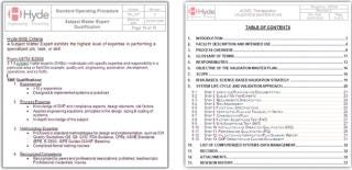
Example documents: ()
Step 2: Project Planning
A project plan defines the E2500 approach, identifies systems within scope, and sets a timeline for design through qualification activities. A standard operation procedure (SOP) or validation master plan (VMP), can document and justify the E2500 approach for specification, design, and qualification of systems. Although E2500 is an industry consensus standard, its applicability to regulatory laws and expectations must be justified. The project plan maps the E2500 process to regulatory expectations such as the Food Drug & Cosmetic Act’s section 506A (21 USC 356a), 21 CFR 211.63, and EC Directive 2003/94/EC’s Article 8 and Annex 15. Fo
r example, the standard’s “risk-based and science-based approach to the specification, design, and verification” are consistent with Annex 15’s “A risk assessment approach should be used” and ICH Q9 for quality risk management, which applies risk management “to determine the scope and extent of qualification of facilities, buildings, and production equipment.”
E2500 saves time and reduces costs by encouraging good-quality vendor documentation. According to section 6.8.1, drawings, certifications, test documents, and results “may be used as part of the verification plan documentation.” That eliminates redundant testing and improves quality by leveraging vendor knowledge and prior work. Vendors receive a written qualification after review of their quality systems, technical capabilities, and practices to ensure that their documentation is accurate. According to E2500 sections 6.8.1 and 6.8.3, vendor qualification is approved by a system’s SME and a company’s quality assurance department.
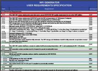
Example documents: ()
Step 3: RequirementsDefinition
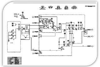
User requirements specifications (URSs) define needs that will provide the “basis for further specification, design, and verification of the manufacturing system,” says E2500 section 7.2. Process engineering SMEs typically develop and approve these requirements based on a company’s needs for capacity, output, process controls, and cleaning/sterilization as well as the operating environment.
Step 4: Specification andDesign
SMEs translate URSs into a system description and functional specifications (FS), which provide the basis for a system’s detailed design. System vendors are often best equipped to develop those specifications. A vendor also can be leveraged to provide both hardware and software design specifications (HDSs and SDSs) as needed.
Step 5: Risk Assessment
At this point, SMEs conduct an FMEA as a design review to identify critical aspects that affect their systems’ installation, operation, and performance. According to E2500 section 8.3.2, risk assessment identifies potential design modifications or supplemental verification testing to mitigate high-risk aspects. Resultant URS and FS revisions are documented with an engineering change notice (ECN) approved by each system’s SME. As the design and fabrication process proceeds, necessary modifications will again be approved by the system SME, who issues ECNs to revise the URS and FS documents. Recommended verification testing is carried forward for critical aspects to the verification plan.
Step 6: Verification Plan
A verification plan provides a systematic approach to verify that manufacturing systems “have been properly installed,” “are operating correctly,” and are “fit for intended use,” as described in E2500 sections 5.1 and 7.4. The plan identifies required documentation and testing and indicates when in the system design–verification life cycle such information is acquired (section 6.6.3.3). A verification plan consists of two documents: an inventory verification list (IVL) and a verification test matrix (VTM).
The IVL identifies all necessary system design and verification documentation and serves as a document-acquisition checklist and an engineering turnover package (ETOP) table of contents. An IVL contains a list of relevant documentation: URS, FS, HDSs, SDSs, piping and instrumentation diagrams (P&IDs), electrical and mechanical drawings, manuals, utility predecessor matrices, a risk-analysis report, a verification testing matrix, and the verification protocol and report.
The VTM is the essence of E2500. It identifies critical testing on the basis of risk levels identified in a risk assessment report, design documentation, and SME input. This document also identifies the chronological point in a system’s life cycle (e.g., factory, installation, start-up, or qualification) when testing will be performed and documentation acquired (E2500 section 7.4.2.1). Noncritical aspects are documented using the IVL checklist and typically do not require the resources or oversight of an SME or QA personnel. However, critical aspects require added SME scrutiny and are documented or tested in a verification test protocol (VTP). Acceptance criteria for a VTP are derived from performance and functional requirements detailed in system design documents (e.g., URS and FS). VTPs list tests to mitigate high-risk aspects as well as tests deemed necessary by SMEs to demonstrate system functionality, features, capacity, and output quality. Such critical tests are generally executed only once, either during factory testing.
As described in section 7.4, a VTP contains only the critical testing necessary to verify that a system is properly installed, that it operates correctly, and that it is fit for its intended use (E 2500 §7.4). A VTP organizes this testing as it pertains to installation/utility verification, start-up/operation verification, and functional/performance verification. Those phases of a VTP also can be used to satisfy the EC Annex 15 qualification requirements. The value of a VTP is in its isolation of critical testing needed to verify a system. According to E2500 section 7.4.2.3, a VTP ensures that this critical testing is reviewed by both an SME and QA personnel. Other testing and document acquisitions are moved to IVL checklists and other systems.
Step 7: Verification Plan Execution
A VTM identifies when testing and document acquisition for the IVL and VTP will occur. Testing may be performed as part of FAT/SAT protocols or may be performed according to test functions within a VTP. Testing of noncritical aspects is more simply verified using an ETOP IVL form.
Because a VTP covers only critical testing, it is executed or overseen by a system SME (E2500 section 7.4.3.1). Critical tests assess system performance and functionality and include more complex testing, such as performance curves and system response attributes. Documentation and test results from the FAT and SAT — including eligible vendor test documentation (section 7.4.3.2) — may be referenced to satisfy test requirements within a VTP. In that case, prior test results would be reviewed and documented by the SME during VTP execution. A key element of such an approach is that testing is not repeated unless results are likely to be affected by transportation or installation. E2500 streamlines the verification approach by eliminating redundant testing that simply doesn’t add value.< /p>
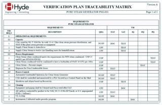
Example documents ()
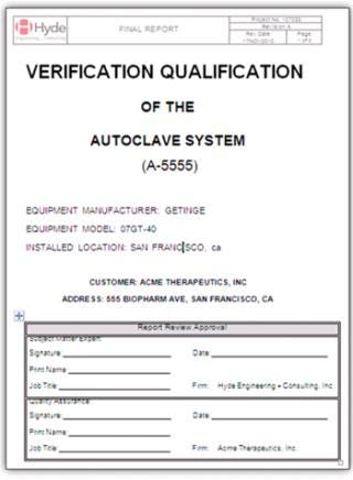
Example documents ()
Effective change management is crucial to the success of this approach. And during execution of a verification plan, a company may find it useful to generate a “punch list” of items to be resolved in subsequent testing or design modifications.
Step 8: System Verification Report
A system verification report overviews and reviews testing conducted during system design, fabrication, installation, start-up, and verification. This report specifically reviews and summarizes all testing for critical aspects as identified in a VTP. Ideally, the report is written by an independent SME, which further mitigates risk by providing an independent review of protocol exceptions, deviations, and punch-list items. This report also documents that punch-list items affecting critical aspects have been satisfactorily addressed. It also summarizes actual system performance data (e.g., capacity and outputs) to compare with user requirements and specifications. That provides added value as a document to reference in defining actual system capabilities.
Based on that review, a system verification report concludes with a statement that indicates whether a system is or is not fit for its intended use (E2500 section 7.5.3). Section 7.5.4 says that this report should be approved by the SME as well as by QA: the SME reviewing technical elements whereas QA provides risk-mitigating oversight to ensure that the design-qualification process was followed and complies with current regulations. So QA serves as the SME for CGMP regulatory requirements, which requires QA personnel to monitor and stay current on international guidance and directives.
Step 9: GMP Release
Final system release for GMP use is performed by QA personnel. QA verifies that a system has been documented as fit for its intended use and that it complies with other GMP systems with respect to personnel training, calibration, maintenance, operating procedures, and change management. Once those elements are verified, QA can issue authorization to release the system for GMP operational use (E2500 section 7.5.5).
Step 10: GMP Operation and Change Management
After release for GMP use, according to section 8.4.3, modifications are controlled through change management with a focus on critical aspects and system performance. Changes to noncritical aspects are authorized by the SME using an ECN form, which streamlines the process for repairs and parts replacement.
Changes to critical aspects are allowed providing that criteria identified in the relevant VTP are satisfied. Change management thus focuses on maintaining system performance rather than identical component replacement. To mitigate risk with additional oversight, changes that affect system requirements relative to product quality and patient safety are additionally approved by QA (E2500 sections 8.4.2 and 8.4.3).
For Efficiency’s Sake
The E2500 approach streamlines design qualification by focusing on design and verification of critical aspects of a manufacturing system that affect product quality and patient safety (Figure 1). This is accomplished through qualified SMEs providing technical input and risk assessment as a means of identifying and justifying those critical aspects. Routine testing and document acquisition are moved to checklists and other GMP systems, which allows verification to focus on high-value system performance elements. When carefully implemented, the E2500 approach can effectively reduce the testing, staffing, costs, and time associated with the design-qualification phase of a system’s lifecycle.
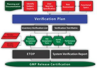
Figure 1: ()
About the Author
Author Details
Peter K. Watler, PhD, is principal consultant and chief technology officer of Hyde Engineering + Consulting, 400 Oyster Point Boulevard, Suite 520, South San Francisco, CA 94080; 1-415-235-1911; [email protected]; www.hyde-ec.com.
REFERENCES
1.) ASTM Standard E2500-07 2007. Standard Guide for Specification, Design, and Verification of Pharmaceutical and Biopharmaceutical Manufacturing Systems and Equipment, ASTM International, West Conshohocken.
2.) Working Party on Control of Medicines and Inspections 2001. Final Version of Annex 15 to the EU Guide to Good Manufacturing Practice, European Commission, Brussels.
3.) International Standard IEC-60812 2006. Analysis Techniques for System Reliability — Procedure for Failure Mode and Effects Analysis (FMEA)Second Edition, International Electrotechnical Commission, Geneva.
4.) Military Standard MIL-STD-1629A 1980. Procedures for Performing a Failure Mode, Effects and Criticality Analysis, US Department of Defense, Washington.
5.) ISO/IEC Guide 51 1999. Safety Aspects — Guidelines for Their Inclusion in Standards, Second Edition, International Organization for Standardization, Geneva.
6.) Stamatis, DH 2003.Failure Mode and Effect Analysis: FMEA from Theory to Execution, Second Edition, ASQ Quality Press Publications, Milwaukee.
You May Also Like


