Applying Good Engineering Practices to the Design of Single-Use SystemsApplying Good Engineering Practices to the Design of Single-Use Systems
Significant changes are being incorporated into biopharmaceutical manufacturing processes as a result of drivers such as increasingly strict regulatory demands, reduction of manufacturing costs, and outsourcing to contract manufacturing organizations (CMOs). Historically, many biopharmaceutical processes were designed and built based on cleanable, reusable stainless steel systems and unit operations. Today several industry drivers are shifting some unit operations toward single-use technologies, namely lowered cross-contamination, reduced capital investments, and desired further reduction in manufacturing costs and shortened drug development times (1,2,3).
The general benefits of disposable systems have been described in various case studies and technical articles (4,5,6,7,8,9), but their suitability for each specific process must be assessed individually. One universal requirement, whether a system is single-use or reusable, is the application of good engineering practices and the effective integration of a diverse range of technologies and process operations. This may be easier to achieve for reusable stainless steel systems because of the industry’s greater familiarity with established technologies as well as the availability of knowledge on design and operation of existing processes. The task can potentially be more demanding for relatively new technologies, with which users have limited experience. In such cases, success requires close collaboration with system engineering companies, especially those having experience in single-use systems and technologies.
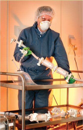
Figure 1:
WWW.PALL.COM
Here we describe a case study in which an integrated single-use system was designed and developed for a CMO (Patheon UK) by a systems supplier (Pall Life Sciences) using appropriate project management tools and good engineering practices.
Outline of Project
The CMO was planning to manufacture clinical trial lots for a new drug within an existing production facility. The process involves contained API powder dispensing and the addition of API and excipient powders into a chilled mixing system with inlet ports for WFI and a pH adjuster. The final product liquid formulation is sterile filtered into a chilled holding vessel and then aseptically transferred from a class 10,000 (Grade C) area to a vial-filling machine through a final sterilizing filter in a class 100 (Grade A) area. The filled vials are then lyophilized.
The preferred manufacturing option was to develop a disposable system and complete that project in six months. Six lots were required, the first three at 20-L scale and the second three at 125-L scale, using 50-L and 200-L disposable mixing systems, respectively.
Project Approach
It was recognized from the outset that the design, development, and effective operation of a multistage disposable system within budget and time limits would present many challenges. A successful outcome would depend on a combination of many factors including a clear project plan; a named management team with defined responsibilities; strong collaboration with disposable system developers and suppliers; successful integration of process technologies and operations; knowledge and expertise on component technology, instrumentation, automation, and system engineering; relevant factory acceptance test (FAT) and site acceptance test (SAT) protocols; and a complete documentation package.
The project details are too extensive to cover fully here, but it is possible to highlight and summarize some key features that enabled this project to be completed successfully within its time constraints. The project was based on a format used successfully for traditional stainless steel reusable systems, incorporating five phases as shown in Figure 1, which also includes typical time schedules for each phase. For a disposable system, those times would be approximately halved.

Figure 1: ()
Project Tender Phase: This important phase required a detailed dialogue between the client and the system engineering company, resulting in a well-defined technical specification that satisfied all user requirements and provided an accurate cost proposal. The key components of this phase were definition of the total process (client user requirements specification, URS); optimization of equipment and materials (system trial and mixing study); selection of appropriate technology; predefinition of the process and instrumentation diagram (P&ID), the single-use component drawing, and automation levels and interfaces; description of the scope of documentation; and technical specification and a final cost proposal.
Project Quality Plan (PQP): The second phase resulted in a plan that described the project team (with rules and responsibilities for execution of the project); all quality activities that must be performed during the course of the project (e.g., validation and FAT/SAT), the relationship between the CMO, the system supplier, and any subsupplier quality actions; a detailed listing of all documentation and certification to be supplied with the system; engineering standards followed during execution of the project; change control procedures; and the project schedule. The schedule was maintained on a detailed Gantt chart showing the timely execution of each project activity and the relationships among those activities.
This level of detail and project management was essential because the project time-scale was critical and required the system to be commissioned and ready for use a short time following approval of the PQP. Despite the time constraints, the plan had to be viewed as a living document, and by agreement it could be revised if required to cover unexpected events. Figure 2 summarizes the framework on which the PQP was developed.
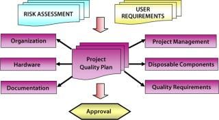
Figure 2: ()
Detailed Design and Function: This phase resulted in a detailed technical specification. The key components of this phase were a final process and instrumentation diagram (P&ID); a collection of single-use (SU) component drawings (drawings that show assembly details, assembly specifications, and packaging specifications for the SU manifolds, with assembly part numbers assigned to form the basis for repeat SU manifold reordering); hardware (equipment, piping, and instrumentation) specification data sheets; single-use component specification data sheets; equipment plot plans; and simple control and functionality narratives (because a detailed functional specification was not required for this project). This phase covered design qualification (DQ), from which installation and operational qualification (IQ/OQ) plans and protocols were created.
Manufacturing and Prequalification: This phase covered the assembly, packaging, and irradiation of the SU manifolds and the assembly of their supporting hardware equipment and instrumentation. Factory acceptance tests followed.
Commissioning and Final Qualification: This phase involved shipment and installation of the system followed by site acceptance testing (SAT). It also included training of maintenance personnel and operators. Wherever appropriate, the FAT and SAT procedures were prepared to support end user qualification documentation, IQ, OQ, and PQ, thus reducing validation efforts overall.
System Design and Operation
Figure 3 shows a simplified schematic representation of the process. The design is based on four separate, single-use manifold systems. The main components of each are described below.
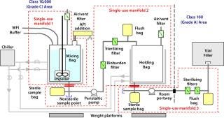
Figure 3: ()
Manifold 1 contains a three-dimensional (50-L or 200-L) cubical compound mixing bag tailored to fit into a double-jacketed stainless steel container for support and product cooling. The container is located on a floor-standing weighing platform to monitor charging of the mixing bags. A bag accepts an impeller, which is encapsulated in a flexible sleeve, for mixing the product. Other items in the manifold include a sampling bag, a compressed air/vent filter, and a sterile connector.
Manifold 2 contains a three-dimensional cubical product-holding biocontainer to fit into a second double-jacketed stainless steel container, which is also located on a floor-standing weighing platform to reconcile the weight of the process batch. Other items in this module include a bioburden-reduction capsule prefilter, a sterilizing capsule filter, a sample/flush bag, a compressed air/sterile vent filter, and a sterile connector.
Manifold 3, the final-stage manifold, contains two sterilizing capsule filters, a sterile sample bag, a flush bag, and a sterile connector. This provides the link from a holding vessel into a class 100 (Grade A) area and vial filling machine.
Manifold 4: In addition to the system described above, the process requires a disposable glove bag and transfer bag for safe handling and addition of active ingredient powder into a mixing bag through a proprietary contained powder connector.
Each system is double-bagged and presterilized by gamma irradiation at a minimum dose of 25 kGy. Sterile connectors on the manifolds enable the complete presterilized system to be assembled in a class 10,000 (Grade C) production area
The major reusable hardware items include a recirculation chiller unit to maintain product solutions at low temperature, a double-jacketed stainless steel bag container, floor-mounted weighing platforms for compounding, a bench-top weighing balance and customized mobile table (for contained API dispensing), peristaltic pumps, and a filter integrity test instrument. The full operating procedures cannot be covered in detail here, but Figure 4 offers a basic outline of the sequence.
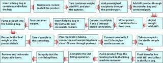
Figure 4: ()
Process Qualification
The disposable system contains a variety of standard disposable components, many of which have a substantial quantity of core validation data and standard operating procedures available and could be incorporated into process qualification documentation. In addition, the suppliers possessed a considerable depth of knowledge and expertise on their products. This situation helped minimize additional qualification requirements, assisting with the project time and cost targets. Nevertheless, the qualification procedures above were vital to the success of the project, and it was essential that comprehensive documentation be available to demonstrate the safety of the process and the final product.
Special attention was required for the bag mixing system in module 1 and the holding system in module 2. Parameters for each process step were established from previous studies, and performance acceptance criteria were defined for inclusion into FAT and SAT protocols. Table 1 lists examples from the FAT and SAT operational protocols for a 50-L scale system. They were designed to demonstrate that it operated according to approved URS. Responsibilities for the operational FAT and SAT protocols were clearly assigned, as shown in Table 2.
Table 1: Examples of acceptance test protocols for a single-use system
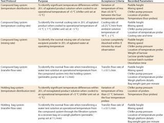
Table 1: Examples of acceptance test protocols for a single-use system ()
Table 2: Supplier and user responsibilities for acceptance tests

Table 2: Supplier and user responsibilities for acceptance tests ()
It can be seen that for a disposable system of this type, the supplier was able to accept a high level of responsibility for the FAT and SAT protocols and execution. Furthermore, the self-contained and portable nature of disposable systems allows similar protocols for factory and site tests, making qualification processes easier. The elimination of cleaning and cleaning validation also facilitates qualification. Time-scales and qualification efforts for an equivalent reusable stainless steel system would differ substantially, with heavier dependence on SAT protocols and users’ resources.
Collaboration Is Key
This project highlights the importance of good engineering practice and systems expertise in achieving a successful multiple-stage and integrated process using disposable components. Through the application of sound engineering and project management principles, this total system was designed, built, tested, delivered, and commissioned within the very tight time-scale requested by Patheon UK.
The approach described here is applicable to all projects involving the implementation of single-use systems and their associated hardware. This project also demonstrates the increasing involvement and responsibility of suppliers when considering introduction of disposable systems into biopharmaceutical manufacturing. This is especially the case for the provision of core validation documentation and validation services to support the use of disposable components, to facilitate end-user risk assessment, and to ease the burden of validation performed by end users. This type of complex project highlights the importance of a collaborative approach for successful implementation of new technologies.
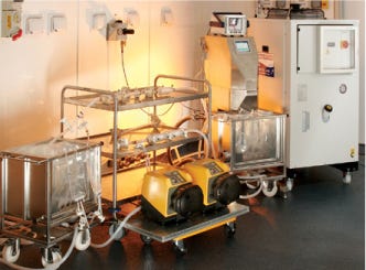
Figure 2:
WWW.PALL.COM
REFERENCES
1.) Langer, E. 2007.Advances in Large-Scale Pharmaceutical ManufacturingSecond Edition, BioPlan Associates Inc., Rockville.
2.) Sinclair, A, and M. Monge. 2004. Concept Facility Based on Single-Use Systems: Part 1. BioProcess Int. 2:S26-S31.
3.) Sinclair, A, and M. Monge. 2005. Concept Facility Based on Single-Use Systems: Part 2. BioProcess Int. 3:S51-S55.
4.) Goldstein, A. 2005. Methods and Considerations for Disposables Implementation: Design, Compliance and Validation. BioProcess Int. 3:S20-S35.
5.) Foulon, A. 2008. Using Disposables in an Antibody Production Process. BioProcess Int. 6:12-18.
6.) Haughney, H, and J. Hutchison. 2004. Single-Use Systems Reduce Production Timelines. Gen. Eng. News 24.
7.) Pora, H. 2006. The Case for Disposable Manufacturing Equipment to Accelerate Vaccine Development. BioPharm Int..
8.) Mach, CJ, and D. Riedman. 2008. Reducing Microbial Contamination Risk in Biotherapeutic Manufacturing: Validation of Sterile Connections. BioProcess Int. 6:20-26.
9.) Fuller, M, and H. Pora. 2008: in press. Introducing Disposable Systems into Biopharmaceutical Manufacturing: A CMO Case Study. BioProcess Int. 6.
You May Also Like


