Integrating Modular Design–Build Execution Strategies into Biotech ProjectsIntegrating Modular Design–Build Execution Strategies into Biotech Projects
One of the earliest and most important decisions in a biopharmaceutical facility construction project is choosing a project execution strategy. This choice affects cost, schedule, and quality of the immediate project as well as further operations throughout the facility life-cycle.
As technology and best practices evolve in the early 21st century, many biopharmaceutical facility projects are integrating some form of modularization execution strategy to maximize predictable costs, schedules, and quality benefits. The modularization concept can manifest as prefabricated buildings, modular process skid systems and HVAC systems, and preengineered modular construction techniques.
Here we focus on a preengineered modular construction project execution strategy adopted by Cook Pharmica for its new biotechnology active pharmaceutical ingredient (API) contract manufacturing facility in Bloomington, IN. This project won the 2007 Facility of the Year award for facility integration from the International Society for Pharmaceutical Engineering (www.ispe.org). That award confirmed the success of integrating a modularization concept for meeting the goals of this biopharmaceutical facility project.
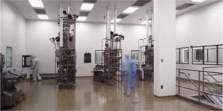
Cell culture room in the Cook Pharmica facility. ()
Background
Back in 1963, a legacy of innovation and quality began in Bill Cook’s spare bedroom in Bloomington, IN. This is where Cook Group, Inc.’s first “factory” was located — where Bill Cook manufactured, stocked, and marketed custom-crafted medical devices. Today, Cook Group is a leader in developing health-care devices used by physicians and hospitals all over the world. With offices worldwide, the company is at the forefront of medical research and product development in minimally invasive medical-device technology for diagnostic and therapeutic procedures.
Cook Pharmica has built a technologically advanced facility with the capacity to expand as its clients scale up from process development through clinical trials and into commercial manufacturing. The company will use mammalian cell culture to produce biopharmaceuticals for clients. Building on the grounds of a former Thompson Consumer Electronics (RCA) television assembly plant, the project was taken from conceptual design to a fully functional, tested, and validated facility in 26 months. It consists of two independent buildings, each encompassing about 450,000 ft2. Other locations were evaluated, but this site’s bilevel layout was ideal for the placement of the bioreactors, which are suspended through the floors between levels.
Project Delivery Approach
Once a business plan and functional strategy for this facility were developed, an in-house team began to examine which project delivery method would best suit the company’s needs. This team established criteria for a delivery approach that prioritized CGMP compliance on a fast-track schedule and emphasized single-source responsibility as the best way to manage the complexity of the project.
“Time-to-market” was an especially important consideration in selection of a project execution strategy. The business case for this new facility included biopharmaceutical industry and patient needs to move products from laboratory to commercialization as rapidly as possible. Return-on-investment (ROI) was another driver for recouping the expense of capital for facilities and equipment, operations, engineering, construction, start-up, commissioning, and validation.
Modular systems with preengineered performance criteria served as the foundation for this project. Inherent benefits of modular methodology include concurrent engineering and procurement tasks. Combined with the compressed field activities of modular construction and integrated commissioning–validation approach, this effectively reduced the overall schedule while ensuring regulatory compliance at every phase of the project lifecycle (Figure 1). The company maximized modular construction benefits by integrating a preengineered, modular CGMP architectural cleanroom core, mechanical systems, building automation, and modular process equipment.

Figure 1: ()
After a rigorous due-diligence process, Cook established a cross-functional project team of modular system design-and-build experts. This team included members from AES Clean Technology, Inc. (www.aesclean.com) for preengineered modular cleanroom systems, CRB Consulting Engineers, Inc. (www.crbusa.com) for modular process expertise, and a local construction firm, R.L. Turner, Inc. (www.rlturner.com). The team would combine preengineered, modular construction with a coordinated facility design and construction approach for flexibility.
Applying the Concept
High-level coordination among team members was critical to identifying roles and responsibilities during the early stages of this project. The result was a documented matrix of responsibility that helped to minimize the duplication of efforts and eliminate gaps in the scope of work.
Design Process: The first part of this project involved transferring a vision and technology developed by scientists in research and development to the facility project team. Initially, Cook Pharmica retained engineers, architects, and specialist consultants to establish space programming and develop a project concept and performance specifications. That delivery approach allowed the in-house team to maintain active involvement with ongoing review of the conceptual design through facility construction. The cleanroom design team thus began with a conceptual design, the first of the three phases of construction documents, followed by schematic and detailed designs, the second and third phases.
Conceptual Design Phase: The conceptual design phase is one of the most challenging aspects of facility design. On one hand, cleanroom designers need to understand the quality and production process implications of their work. On the other hand, the production team must understand how regulations guide these designs and impose certain limitations on engineers.
2007 ISPE FACILITY OF THE YEAR AWARD: FACILITY INTEGRATION
Project: “Project Phoenix”
Location: Bloomington, Indiana
Size: 124,000 ft2 Cost: US$70 million
Key Project Participants: CRB Con
sulting Engineers, Inc.; Mussett Nichols and Associates; G.S. Ridgway & Associates; R.L. Turner Corporation; AES Clean Technology, Inc.; Harry J. Kloeppel and Associates; Commissioning Agents, Inc.; Harrell-fish, Inc.; Cassady Electrical Contractors, Inc.; Project Planning and Delivery; Trane; Spriax/UltraPure; Cummins, Inc.; the Rovisys Company, Inc. (Emerson Delta V); ESC; Cleaver-Brooks, Inc.; YORK; Baltimore Air Coil (BAC); ABEC; Wave Biotech; Westfalia Separator; IPEC; Millipore; Pall Corporation; Mueller and DCI; Cornerstone Flooring and Linings; and Siemens Building Technologies, Inc.
Timeline: Start December 2005, target completion date Q4 2006, contract signed December 2006
Early information in this project consisted of the specific space type, the plan of departments that would occupy that space, and the requirements of scientists and others who would work there. Discussions with key scientists and process experts led to early user requirements in the form of basic system descriptions, simple flow diagrams, and utilities requirements.
Once preliminary process flows had been sketched out, the architects used block diagrams to create conceptual floor plans. Working with minimal input, the engineers provided essential preliminary utility information. Using some general rule-of-thumb values (e.g., airflow per square foot and square foot per cooling ton), they identified heating and cooling loads for the building, thereby establishing utility requirements for the master plan.
Those HVAC building loads were used to estimate potential electrical use and peak demand loads that the facility would have to provide in support of its process requirements. Table 1 illustrates utility requirements determined from the HVAC and process equipment loads. From that early information, AES created an order of magnitude (OOM) budget based on previous experience and benchmark costs from similar projects. Included with that budget was a basis of design (BOD) narrative, which can be an invaluable document for project scoping. It helped the team discover gaps so that funds could be allocated to cover those areas.
Table 1: Preliminary master utility summary (*included within above values)
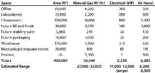
Table 1: Pr eliminary master utility summary (*included within above values) ()
Schematic Design (Program) Phase: Conditions of a manufacturing and storage environment must be controlled closely for compliance with current good manufacturing practice (CGMP) regulatory requirements. In addition, the latest ISO standard (14644) provides guidelines for cleanroom classifications (3).
With over 450,000 ft2 of usable manufacturing space in the first building, our initial efforts concentrated on space planning to allow for future expansions with little impact on the initial manufacturing train. Therefore, phase one of the project concentrated on renovation and construction of 124,000 ft2 of that first building. Within this area, design and construction efforts were dedicated to manufacturing and support areas (office areas, one manufacturing train, support laboratories, warehouse, and process utilities designed to support up to two manufacturing trains).
Renovation of an existing building lent itself well to a modular approach for construction of the manufacturing area. The first cleanrooms were strategically placed adjacent to the office space, which left us with the most efficient layout of unoccupied space for future manufacturing expansion.
Preengineered, modular PVC-coated wall and ceiling systems met GMP requirements for classified spaces by providing nonshedding, nonporous surfaces that resist microbial and fungal growth and can withstand repeated cleaning and sanitization using various chemical solutions (1). These wall and ceiling panels were constructed and finished in the AES factory. Panels were designed to allow future reconfiguration with a single-joint detail that created a flush, continuous wall and ceiling installation using welded joints and fully swept cove details at the floors and ceilings. Standard wall panels were mounted on a 4-in.–high floor track, which was adjusted to suit the site conditions and accept the flush-coved, resinous flooring surface.
A walkable ceiling was constructed of load-bearing, homogeneously constructed sections to withstand an imposed load with a deflection limit of 1:360 on a 10-ft clear span and to support a load limit of 15 pounds per square foot. All openings for lights, fixtures, and fittings were factory formed in each panel prior to delivery. The ceiling panel sections were 4 ft × 10 ft wherever possible to minimize the number of joints necessary.
The walkable ceiling panels were supported from a suspended steel system. The primary suspension system used extruded aluminum alloy ceiling beams supported by drop rods threaded to a turnbuckle, which allowed accurate laser leveling of the flush ceiling system. The drop rods were installed at a maximum of four feet on center along the length of the ceiling beams, which were spaced on 10-ft centers providing for 10-ft open bays. All wall-to-wall and wall-to-ceiling junctions were trimmed with a white PVC coving system that had vacuum-formed corner pieces to allow efficient cleaning and decontamination of the facility.
Modular door systems with PVC finishes were used to provide an aesthetic, high-tech cleanroom. The door fames were designed to produce a flush-frame detail with the adjacent wall panel system. The doors were operated with automatic door openers. Door position switches were installed at all gowning and airlock door locations, with connections to a localized GO/NO-GO (red/green) light alarm system.
Modular glazed windows provided a flush, ledge-free finish throughout the cleanrooms. Maximized visual areas were created to support the company’s goals for a facility with full exposure and optimized operator comfort.
The flooring for this project was crucial to maintaining cleanliness. Product and personnel traffic throughout the new facility would be significant, so a clean, durable surface with good traction was needed. Critical core manufacturing areas received an epoxy flooring system with a polyurethane mortar base designed to address variations in the floor slab.
The cleanroom core was architecturally designed in accordance with IEST lighting standards (from the Institute of Environmental Sciences and Technology, www.iest.org) and federal/ISO critical environment standards to create an environment for contract manufacturing (2). Each process suite was separated from the other suites by entrance and exit airlocks off the main communicating corridors. This design lent itself well to close-coupled process steps while reducing the risk of contamination. The manufacturing areas were constructed to be compliant with FDA and ICH requirements for personnel, equipment, materials, and bulk product flows.
At this point, temperature, humidity, pressure, and air-change requirements were established for the cleanrooms. A “room data sheet” was created for each cleanroom, providing data AES would use to develop the BOD. Those would become facility design criteria in constru
ction documents to be used by a construction qualification team. Table 2 displays examples of design criteria for the project.
Table 2: Facility design criteria

Table 2: Fa cility design criteria ()
Heating and cooling requirements of this project were driven by a need to balance operator comfort and environmental control for products. The cleanrooms are designed to maintain 68 °F ± 5 °F and 30–60% relative humidity to control electrostatic charge, microorganism growth, and personnel perspiration. Make-up air was used as ventilation for personnel and to provide pressurization for environmental control. Directional air flow was used to control pressurization, preventing the migration of particles carried by the air stream from less-clean to cleaner areas, and to ensure cleanliness in the most sensitive areas.
With this type of building, overall pressure comes from leakage cascading from cleaner to less-clean zones, ultimately flowing out of the cleanroom area (pressure cascade). An FDA guideline defines room pressure relationships for two important areas of exposure to drug product quality: critical areas and controlled areas (4). Critical areas (where sterile dosage forms and container–closures are exposed to the environment) should have a positive pressure differential relative to adjacent less-clean areas (0.05 in. H2O is acceptable). In controlled areas (where unsterilized product and in-process product and container–closures are prepared), a positive pressure differential of at least 0.05 in. H2O is acceptable (with all doors closed) relative to adjacent uncontrolled areas. When doors are open, outward airflow should be sufficient to minimize ingress of contamination.
For this project, room pressure differential was designed as follows: Across same-room classification, differential pressure was maintained at 0.02 in. H2O and across different room classification, differential pressure was maintained at 0.05 in. H2O. Although it is acceptable to design for static balanced air systems, active pressure control ensures that when doors are opened, airflow continues to move in the specified direction. Automatic control dampers were implemented into this design to guarantee control of room pressure differential and directional airflow.
We used airlocks to help maintain air pressurization differentials and directional airflow between adjacent areas. Each airlock’s cleanliness classification and airflow rate also matched the classification of the room that it entered into (Table 3). The main reason to maintain high airflow rates in airlocks is to reduce time for pressure build-up between door openings while preventing cross contamination between adjacent rooms.
Table 3: Cleanroom air changes per hour for different classifications of cleanroom
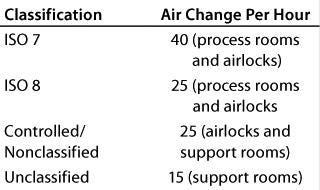
Table 3: Cl eanroom air changes per hour for different classifications of cleanroom ()
Heating and cooling load calculations began after a preliminary floor plan was established. More substance is added to such calculations — taking into account fenestration, lights, people, and equipment heat gains — as end-users finalize their process equipment selections. Preliminary heating and cooling equipment selections determined the required utility infrastructure: chillers, pumps, cooling towers, steam boilers, and heat exchangers.
The process rooms were grouped based on process similarities and room classifications, which resulted in 12 separate air-handling systems with similar temperature, humidity, and filtration requirements. Grouping similar process rooms this way allows recirculation of the return airflow, which helped reduce operational costs. The main advantage of having multiple systems rather than a few “once-through” airflow systems was a 33% capacity reduction of the required cooling tonnage and associated energy use. The 12 air-handling systems each use two levels of mixed-air filtration (95% prefilters with terminal HEPA filters), a steam preheat coil (as required) and a chilled water cooling coil, a hot water reheat coil, and a variable frequency drive (VFD) controlled centrifugal supply fan. Air handlers serving the production suites dehumidify 100% of the airflow through the cooling coil (Figure 2).
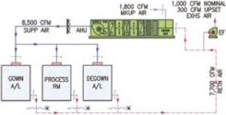
Figure 2: ()
The air-handling systems will operate all day, every day, year-round for contamination control. So each air handler serving a corridor area was designed with a bypass section that allows a portion of return air to bypass the cooling coil because the airflow required for room classification is greater than the room cooling load. This configuration allows return air to mix with precooled supply air to maintain temperature, thereby reducing both cooling and reheat requirements. It reduced cooling from 50 to 30 tons, a 40% reduction (Figure 3).
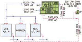
Figure 3: ()
The speed of air supply fans is regulated through VFDs and controlled by velocity pressure sensors in the supply duct that will save energy cost around 11% of each fan’s power consumption (∼$1,460/year). That figure is based on filter loading of about a 1-in. water-column per
year, running constantly ∼340 days, with an electricity unit price of $0.08/kwhr. Payback on those VFDs should be seen within two years.
Preliminary equipment layouts began at this stage because it was important to establish the locations of prime HVAC equipment such as air handlers, chillers, and boilers. Structural engineers worked to design the most efficient steel support system that would work within building constraints. Most cleanroom ceilings were 10 ft high, so 9.5 ft of clear interstitial space remained to house a new structural support system for air handlers, ceilings, ductwork, and piping.
Airflow diagrams were created after the room airflow requirements had been established and were a vital design tool for scope review. From the information developed during the schematic phase. The cost estimate was further developed from the OOM budget as firm quotes were received from equipment vendors and subcontractors.
Detailed (Construction) Design Phase: After the floor plan was finalized and heat gain information from process equipment confirmed, our engineers finalized the facility’s cooling load calculations. Table 4 lists the final HVAC cleanroom check figures. Final airflow diagrams were created and equipment selections then completed. Engineers began detailed design layouts of air handlers and ductwork. Process and utility piping systems were coordinated into the design to allow for proper pitch in the piping systems (process and utility steam), all coordinated with the support structure.
Table 4: HVAC cleanroom check figures for different classes of cleanroom — and the total for all of them
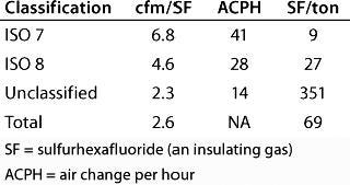
Table 4: HV AC cleanroom check figures for different classes of cleanroom — and the total for all of them ()
A construction cost estimate was further refined into a guaranteed maximum price with shared savings on the final project cost. Table 5 shows the various activities for each discipline.
Table 5: Various phases of design development

Table 5: Va rious phases of design development ()
Quality and Commissioning
Through a comprehensive quality plan (created and approved with Cook Pharmica’s quality assurance department), spreadsheets were used to record the receipt, installation, and start-up of equipment and products. This process verified construction and installation as demanded by good engineering practices (GEPs) as well as installation qualification (IQ) for systems identified as directly affecting products manufactured in the facility (direct impact).
Operational support included a testing, adjusting, and balancing (TAB) contractor along with a third-party certification contractor. Engineers worked closely with the TAB contractor to verify that each system was within specified airflows and room pressures. QA documents verified GEP operation and operational qualification (OQ) for the systems that were identified as direct impact.
For air balancing, designers assume leakage values to size air-handling equipment. The actual make-up airflow for a particular system will depend on how tightly the room and ductwork are constructed and installed. Once supply airflows are met, the TAB contractor concentrates on room differential pressures. Most balancers want to meet the return airflow values shown on design drawings, although in reality the room pressures are what is validated. Accuracy of the return airflow compared with design values is directly proportional to the quality of a system.
While the balancing was performed, engineers worked very closely with the owner’s automatic temperature controls (ATC) contractor to create a document that tested the readiness of the systems to be turned over to the commissioning–qualification teams. For a functional test of the active pressure control system, a series of computer screen shots were taken from the building automation system. The first was a static display showing all doors closed to prove that the rooms were within spec and under control. Then one room’s door was opened, and a second screen shot was taken to display the control dampers reacting in the proper direction as required to maintain the directional airflow. That test challenged several systems working together to verify that the performance of the systems met the operational qualification of direct-impact systems. The validation team leveraged this commissioning and qualification report to eliminate additional testing during IQ and OQ.
Results of such tests were included in the engineering turn-over package (ETOP) and used to prove that all systems and equipment met established user requirements specifications (URS) as well as end-user expectations. The commissioning process verified that “what was specified was installed, that it functions properly, and that it was successfully turned over to the end user.”
Modular Project Benefits
Cook Pharmica had selected a modular execution strategy as an alternative to stick-built or other options as the best approach to meet its project goals. The company established a cross-functional team of design–build experts as the best way to manage the complexity of this project instead of using typical design–bid–build methods.
It was strongly committed to collaboration for achieving a fast, effective, cost-controlled, and fully integrated project. The congenial team, with the company’s confidence and respect in its critical capabilities, infused the project with loyalty, pride, and a unified vision. Routine peer review of the whole project allowed the team to address the kinds of issues that arise hourly, daily, and weekly on a typical construction project. A high level of coordination and communication within the team benefited schedule, quality, and cost.
Compared with traditional modes, the modular construction sequence, methods, and procurement strategy yielded better scheduling resulting in faster construction of the GMP space. Conventional construction of the office space and non-GMP areas was concurrent with the modular cleanroom system to deliver the overall project more rapidly. Early integration of modular process and cleanroom system experts into the project team supported proper allocation of resources and accurate cost analysis to create a high-quality integrated design. In collaboration with one another, the team members optimized modular systems design and construction to reduce costs. Customer and vendor quality teams were involved from the earliest stages to contribute their shared and unique abilities in validation and commissioning the facility for biomanufac
turing. Preengineered modular systems manufactured in factory-controlled conditions and assembled in the field ensured predictable, repeatable quality form, fit, and finish results.
Design–Construction Integration: Concurrent cross-functional engineering and design activities allowed this project’s cleanroom designers to create detailed panel layout drawings for fabrication of the modular architectural systems while the engineering team was finalizing the design. Designers integrated the architectural features and mechanical systems using preengineered return-air wall details that eliminated sheet-metal ductwork below the cleanroom ceiling level. Captured in the detailed design phase of the project, the innovation manifests in the construction phase as cost savings and construction schedule improvement because no return air duct had to be installed in that space. Designers then integrated architectural and electrical systems with preengineered, UL-approved electrical paths within the prefinished walls. This integration was also captured in the detailed design phase of the project. It created cost savings and schedule improvement in the construction phase by eliminating a code inspection step in the field and speeding the installation of wires and cables.
Also during the design phase, architectural and process system components were integrated into the design. These include remote-mounted electrical panels and piping-transfer panels within the prefinished walls. The apertures were coordinated and cut at the factory during fabrication. This integration was closely coordinated during design to improve the construction schedule by allowing process equipment to be installed in the field without sacrificing factory designs.
Early Procurement: Once equipment selections were approved (before completion of the detailed engineering drawings), all long–lead-time items were identified and released for procurement, including air handlers, a packaged chiller plant and a boiler plant, utility pumping skids, process equipment skids, and the modular architectural systems.
Construction Benefits: The walk-on ceiling system reduced the project schedule because much wiring, ductwork, and control activities could be completed by workers on top of the ceiling while room finishes were being finalized. The end result was a CGMP room-side ceiling finish and a topside maintenance platform all within a single system. This gave field construction benefits in cost, flexibility, and adaptability.
Preengineered modular systems were combined in the field to create the cleanroom facility, minimizing the amount of on-site labor and thereby reducing project cost. Preengineered modular construction methodology excels in productivity over stick-built construction (Figure 4).
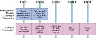
Figure 4: ()
Another significant advantage to modular project execution is increased flexibility. The collaborative team planned for late-arriving process equipment during construction by including access paths. The flexibility of a field-assembled modular cleanroom system meant that wall sections could be left open to accommodate late-arriving large pieces of equipment into the rooms for installation. Following clean-build protocol (an inherent attribute of modular systems), the installers closed those spaces afterward with no concern for contamination of the equipment itself or the utilities that serve it.
Integration Saves Time and Money
The most significant benefit to Cook Pharmica was an accelerated construction schedule with its associated cost benefits. The integrated approach to engineering, procurement, and construction created time savings that were enhanced through well-planned commissioning and qualification. The quality assurance group maximized its efforts by including the commissioning–validation team as part of its structure. That integration ensured FDA and ICH compliance in terms of personnel, equipment, materials, and bulk product flows. After construction, commissioning and qualification efforts were supported by the design team to assist in completion of the IQ/OQ testing while reducing the schedule and saving project costs.
Design of the manufacturing areas began in July 2004. Construction started in February 2005 and was completed in December 2005. Commissioning and qualification began in December 2005, and the facility was turned over to validation by April 2006.
The company has reported that based on its experience with other building methods, this approach has had significant impact on time-to-market and cost. Speed in decision-making (especially for change orders) and aggressive engineering efforts led to about a 9% savings on total engineering costs — a big difference when millions of dollars are being spent. This project is testimony to the fact that integration of engineering, procurement, and construction activities for a project while working closely with commissioning and qualification teams will reduce overall construction schedules — and therefore, project cost.
FACILITIES ENGINEERING GLOSSARY
You’ll find definitions of many less-familiar terms from this article online at BPI Extra! this month:
www.bioprocessintl.com/bpiextra
REFERENCES
1.) Biopharmaceutical Manufacturing Facilities Task Team 2006.Table 4–1Pharmaceutical Engineering Guides for New and Renovated Facilities, Volume 6: Biopharmaceuticals, International Society for Pharmaceutical Engineering, Tampa.
2.) American Society of Heating, Refrigerating, and Air Conditioning Engineers 2003.Chapter 16: Clean SpacesHVAC Applications Handbook, ASHRAE, Atlanta.
3.) Institute of Environmental Sciences and TechnologyISO 14644-1: Part 1 — Classification of Air CleanlinessCleanrooms and Associated Controlled Environments, IEST, Arlington Heights.
4.) CBER/CDER/ORA 2004. Guidance for Industry: Sterile Drug Products Produced By Aseptic Processing, US Department of Health and Human Services, Food and Drug Administration, Rockville.
You May Also Like


