Investigating Flow Distribution and Its Effects on Scale-UpInvestigating Flow Distribution and Its Effects on Scale-Up
Depth filtration is widely used in the biopharmaceutical industry to purify target proteins by removing whole cells, cellular debris, fines, aggregates, and colloidal particles from the fermentation broth (1,2). At large scale (>2,000 L), culture harvest from a bioreactor is typically processed with a disc-stack centrifuge to remove cells and cell debris. Although centrifugation is very effective for removing whole cells and larger debris, it cannot remove small-size particles, which remain suspended in the centrate. Depth filters are commonly used after centrifuges to remove smaller impurities before further processing downstream.
Accurate scale-up of bioseparation unit operations adds value by expediting a development process and allowing for the use of lower safety margins in sizing filtration area, which improves process economics.
PRODUCT FOCUS: BIOLOGICS
PROCESS FOCUS: Recovery and separations (downstream processing)
WHO SHOULD READ: MANUFACTURING AND PROCESS ENGINEERS
KEYWORDS: HARVESTING, DEPTH FILTERS, CENTRIFUGATION, SCALE-UP, PRESSURE, PROCESS ECONOMICS
LEVEL: ADVANCED
For depth filtration, the scale-up criteria are to use the same filter media, operating flux, feed volume per unit area of filter media, feed solution, and temperature. To process large quantities of fluid, one approach is to vertically stack several capsules containing depth filter media. For such systems, it is important to develop an understanding of flow distribution, which in turn affects the operating flux across each capsule and thus filtration performance.
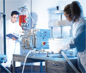
Figure 1:
PALL LIFE SCIENCES (WWW.PALL.COM)
Large-Scale Depth Filtration
To process large quantities of centrate, multiple depth filter capsules are often used in parallel within a filtration chassis (Figure 1) (1). A vertical arrangement of capsules is preferred over a horizontal arrangement for various reasons including ease of installation, preuse venting and draining of the assembly, as well as reducing the footprint for the overall system (3). A stacked system is designed to operate in multiple configurations based on the location of feed and filtrate ports (Figure 1). Within such systems, although all the capsules are connected in parallel, variations in differential pressure are expected, and therefore velocities will vary across different capsules (4,5,6).
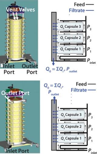
Figure 1: ()
It is well known that the differential pressure across a filter medium affects both flux and volumetric throughput, which is described by filtrate volume per unit area of depth filter media (7). To date, little work has been done to examine the effects of such variations on the scalability of depth filtration systems (3,8). We investigated the effects of operating flux and various inlet–outlet configurations on the pressure profile across a vertically configured stack of depth filter capsules held in place within a stainless steel chassis (Figure 2)—and the subsequent effects on their filtration capacities.
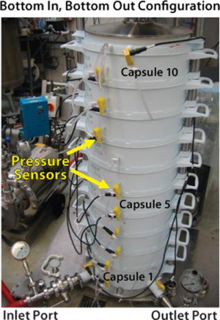
Figure 2: ()
Materials and Methods
To evaluate the effect of operating flux and inlet–outlet configurations on the pressure and flow distribution in a multiple-capsule system, we conducted water flow tests through 10 capsules (total effective filtration area of 20 m2). Each capsule contains depth filter media encapsulated in a cage-like structure, which provides support and serves to distribute feed solution to the available filter area. We tested single-layer depth filter media with a retention rating of 0.1–0.3 µm and a filter permeability of 120 LMH/psi (1,764 LMH/bar) with both inlet–outlet configurations (Figure 1).
A single-layer depth filter capsule has twice the filter area of dual-layer media in the same size capsule. So a single-layer capsule will require a higher flow rate at a given feed flux, which in turn increases pressure loss associated with the filtration system. Our water flow tests were performed at three fluxes (100, 200, and 300 LMH) spanning the typical operating range for depth filtration applications in biopharmaceutical processing (9,10). On the feed side, pressure for each capsule was recorded using specially installed pressure sensors along the height of the system (Figure 2). Pressure on the filtrate side was measured at the top and bottom of the system, and we assumed a linear profile for the pressure drop along the filtrate manifold. Figure 3 shows differential pressures across each capsule, normalized with respect to the differential pressure across capsule 1 (at the bottom of the stack), for various inlet–outlet configurations and fluxes.
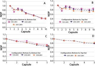
Figure 3: ()
Results and Discussion
As expected, for both configurations hydrostatic pressure does not affect the relative differential pressure across the capsules because the feed and filtrate sides across each capsule are at the same height — and therefore will have the same magnitude of hydrostatic pressure. The main driver behind differences in the profile of differential pressures for the two configurations is the direction of flow in the feed and filtrate manifolds. Figure 3 shows that a more uniform differential pressure distribution is achieved with bottom-in, top-out configuration. Flows in the feed distributor and filtrate collector are concurrent (Figure 1B), and differential pressures across the 10 capsules were within 30% of each other. For five-capsule systems, the difference was even smaller (<20%).
Although, as expected, the differential pressure across each capsule increases with increasing flux (data not shown), the uniformity of differential pressure along the system is not affected by the magnitude of flux (Figure 3). Increasing fluxes within such a system can affect pressure distribution in two ways. First, pressure drops in the feed and filtrate manifolds will increase because of higher flow rates associated with higher flux. Second, pressure drop in the feed distributor will decrease as result of fluid transfer across the capsules — thus decreasing the fluid velocity. A similar but opposite trend will be observed in the filtrate collector as a result of receiving additional fluid across the capsules. Understanding the relative contribution of these effects will require further investigation and remains outside the scope of this report.
We then investigated the effect of differential pressure variation on the filtration capacity of a multicapsule system. To eliminate variations resulting from media lot variation, we used the same lot for all filter capsules. The challenge solution was a mixture of homogenized yeast and whole yeast to simulate a mammalian cell culture.
All the filters were first flushed with water to the recommended volumetric throughput. The challenge solution was then filtered at flow rates calculated based on a system average flux rate of 300 LMH. Pressures were recorded across each filter capsule and at the inlet and outlet of the system. For throughput comparison, we used the differential pressure across inlet and outlet of the large-scale system. Figure 4 reports the relative performance of one- and 10-capsule systems. Throughput values for the large (20 m2) and scaled down (2 m2) systems lie within 2% for the bottom-in, top-out configuration (Figure 4A). As Figure 4B shows, the performance of a 10-capsule system is much closer to that of a single-capsule system with the bottom-in, top-out configuration.
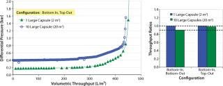
Figure 4: ()
We investigated the evolution of pressure distribution as a function of throughput to determine whether the differential pressure increase was significantly different for different capsules. Figure 5 shows pressure profiles for both bottom-in, bottom-out and bottom-in, top-out operating configurations plotted against system throughput normalized with a single-capsule system. The profiles show that as filtration proceeds, the difference in differential pressure across the top and bottom capsules remained essentially constant until late stages of filtration, which suggests that each capsule is operating independently. During the late stages, a similar magnitude of differential pressures was recorded across all 10 capsules. The effect was more noticeable with the bottom-in, bottom-out configuration (Figure 5A). The dataset (Figure 4B and Figure 5) strongly suggests that an improved scale-up performance with bottom-in, top-out configuration resulted from a more uniform pressure/flow profile across different capsules (Figure 3).

Figure 5: ()
Our results show that an understanding of the fluid mechanics and flow distribution in a multicapsule depth filtration system is essential to achieving optimal performance and good scale up with relatively lower safety margins to improve overall process economics.
REFERENCES
1.) Meltzer, TH, and MW. Jornitz. 2007.Filtration and Purification in the Biopharmaceutical Industry 2nd Edition, CRC Press, Boca Raton.
2.) Shukla, AA, MR Etzel, and S. Gadam. 2006.Process Scale Bioseparations for the Biopharmaceutical Industry, CRC Press, Boca Raton.
3.) Anderson, S, M Collins, and M. Muehl. 2009.Expanding Disposable Depth-Filter Applications: Pall Focuses on the Improvement of Process Clarification OperationsGen. Eng. News:46-47.
4.) Koh, J-H. 2003. Pressure and Flow Distribution in Internal Gas Manifolds of a Fuel-Cell Stack. J. Power Sources 115:54-65.
5.) van Reis, R. 1997. Linear Scale Ultrafiltration. Biotechnol. Bioeng. 55:737-746.
6.) van Reis, R, and A. Zydney. 2001. Review: Membrane Separation in Biotechnology. Curr. Opin. Biotechnol. 12:208-211.
7.) Graddison, AS, and MJ. Luis. 1996.Separation Processes in the Food and Biotechnology Industries: Principles and Applications, Woodheaad Publishing, Cambridge.
8.) Muehl, M, and D. Sievers. 2009.Wirtschaftlicher Trennen Pharma + Food, Woodheaad Publishing:40-42.
9.) Rathore, AS. 2004.Optimization, Scale-Up, and Validation Issues in Filtration of Biopharmaceuticals, Part 1BioPharm Int., Woodheaad Publishing.
10.) Lutz, H. 2009.Considerations for Scaling Up Depth Filtration of Harvested Cell Culture FluidBioPharm Int., Woodheaad Publishing.
You May Also Like


