Large-Scale, Single-Use Depth Filtration SystemsLarge-Scale, Single-Use Depth Filtration Systems
Clarifying cell culture broth is the first downstream unit operation in an elaborate sequence of steps required to purify a biological therapeutic. A combination of centrifugation, depth filtration, or tangential-flow filtration (TFF) is used for that operation. The availability of largescale, single-use, depth filtration technology in the recent years, however, has given process developers the capability to improve and simplify downstream processes.
Clarification of Cell Culture Streams
The main purpose of clarification is to efficiently separate cells, cell debris, and other colloidal matter and deliver a particle-free feed to downstream processes such as protein A capture chromatography. Various commercial technologies are available for this purpose. Figure 1 presents schematics of centrifugation, flocculation, TFF, and depth filtration combinations that are used in bioprocessing.
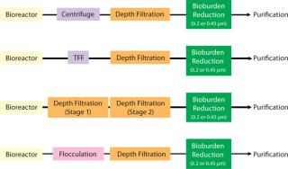
Figure 1: ()
When only depth filtration (also referred to as depth microfiltration or prefiltration) is used at this step, it is often conducted in two stages. First, a filter with an open-pore structure removes cells and cell debris. Then a filter with a tighter pore structure removes colloidal matter. Depth microfiltration is discussed in greater detail in the next section.
Flocculation with polymeric resins or chitosan followed by depth filtration is also an efficient method for primary clarification of high-density cell culture broths (1). To reduce bioburden and prevent plugging of downstream chromatographic columns, the clarifying step is followed by filtration with 0.45- or 0.2-µm membranes. Process developers’ decisions of what clarification approaches to use are based on the characteristics of their harvest solution, separation needs, validation requirements, and ease of implementing chosen technology in production operations.
Centrifugation with disk-stack bowls is a well-established technology for clarifying cell-culture broths. This process, however, can be challenging in biopharmaceutical streams. Cell-culture solutions have a broad range of particle sizes. When those solutions are homogenized, the particles can be small and highly hydrated. Such particles can have a density that is very close to that of the bulk liquid. Furthermore, due to cell-shearing and/or presence of nonviable cells, intracellular components such as nucleic acids can significantly increase harvest stream viscosity (2).
With improved centrifuge designs, process developers have optimized their operating conditions. Centrifugation is a preferred method for clarifying cell cultures from batch sizes >2,000 L (3). Nonetheless, centrifuge centrate still does not have the requisite clarity for downstream processing. In addition, current upstream processes are delivering cell densities of >150 million viable cells per milliter and monoclonal antibody (MAb) titers of >25 g/L. So the limitations of centrifugation processes for high cell-density harvests are again becoming a challenge (1). Hence, invariably, depth filtration is used after the centrifuge step.
Tangential-flow filtration (also referred to as cross-flow filtration or CFF) with microfiltration membranes has become a popular technique for clarifying bioprocess culture broths. A major advantage of a TFF process is that it produces a relatively clear stream that requires minimal filtration before loading on a protein A column. Cross-flow microfiltration membranes have a high initial flux. So if the transmembrane pressure is not controlled well during startup, it rapidly creates a fouling layer. That makes the flux drop to a fraction of its initial value.
Further, because a TFF device concentrates the feed, formation of a gel polarization layer on the membrane surface is unavoidable. The total amount of suspended solids that can be handled by a cross-flow microfiltration is determined by viscosity limitations of the pump and the channel diameter of the TFF device. The concentration factor — and hence the percent of feed recovered as permeate — can be limiting for high–cell-density cultures. In addition, because the membrane’s upstream side is constantly kept in circulation, the risks of cell breakage and shear damage must be considered. For those reasons, TFF is not often a first choice for a clarification step (3).
Depth Microfiltration
Due to its low initial cost and ease of validation (compared with centrifugation and TFF devices), depth filtration is widely used for the clarification of cell culture harvests (4). Depth filtration functions as a workhorse filter and provides a cost-effective solution by trapping contaminants that would otherwise plug a final polishing membrane filter.
Most depth filters used in biopharmaceutical processes are made of cellulose fibers and filter aids (e.g., diatomaceous earth) bound together by a polymeric resin that provides the necessary wet strength and imparts a cationic surface characteristic. Depth filters are made by a wet-laid process, similar to that used for paper making. They are first made into flat sheets, which the biopharmaceutical industry uses in conveniently fabricated lenticular disk/cartridge formats that can be assembled into multistack housings (Figure 2A).
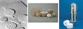
Figure 2a: ()
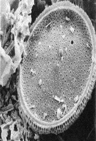
Cellulose fibers form a filter’s matrix. A filter’s void volume (porosity) and particle-retention rating are created by controlling the lengths of those fibers and how well they are compacted in a filter bed. The fibers’ degree of compaction directly correlates to a filter’s permeability and retention characteristics. The tighter the compaction, the better it retains small particles, which lowers permeability. Adding diatomaceous earth to a filter matrix improves permeability and allows the filter bed to remain tightly compacted. Diatomaceous earth appears as a fine powder to the naked eye, but it has hundreds of submicron crevices when seen under a microscope (Figure 2B). When placed in a fluid path, those honeycomb-like hollow structures trap submicron particles in their crevices.
 lor:#f7f7f7;margin-bottom:5px; margin-right:5px; margin-left:5px;margin-top:5px;cursor:pointer;” >

Figure 2b: ()
A filter’s polymeric resin serves two purposes: to hold a filter matrix together and to impart a charge (usually positive) to the internal surfaces of a medium. That positive charge creates a zeta potential that helps retain colloidal particles smaller than the pore-size of the filter (5).
Cellulose-based depth filters are arranged in lenticular disk cartridges and stacked in large stainless housings (Figure 2A). Those cartridges are designed with an adequate amount of spacing between disks to accommodate accumulating solids. This design gives cartridges enormous capacity to capture cells and cell debris — a capacity not achievable with pleated or string wound cartridges (6).
Large-Scale Depth Filtration
Large-scale depth filtration systems are common in the bioprocess industry. They use multiround stainless housings with up to 16-in. depth-filter modules stacked three or four high to maximize surface area. Figure 3 shows an industrial-scale depth-filtration harvest system consisting of multiple housings and cartridges for clarifying cell harvest from a 15,000-L bioreactor. Before harvest, depth filters are flushed with water or an appropriate buffer to remove loose particulates and extractables from the filter manufacturing process. Once a harvest is completed, the filters are again flushed to recover valuable product held-up in the housings. Harvest yields as high as 95% are achievable using a post-use flush and ensuring minimum product loss (7).
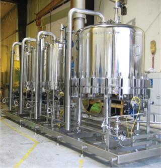
Figure 3: ()
As process volumes increase, handling such housings on a manufacturing floor becomes cumbersome. Filter change-outs require special equipment such as overhead hoists. Users must open housings, remove wet cartridges, install new ones, and ensure that those housings are sealed properly. Further, cleaning in place (CIP) requires that the system be shut down. When change-outs and CIP times are taken into account, depth-filtration downtime can have a great impact on plant efficiency.Switching to a large-scale single-use depth filtration process could offer significant economic benefits. Depth filter systems consisting of stainless steel housings require higher proportion of up-front capital costs. By comparison, the cost of a disposable depth filter is “activity based” and only incurred when a facility is in operation (8). A single-use depth filter allows process developers to implement flexible solutions.
Single-Use Depth Filtration System
The Encapsulated Zeta Plus (EZP) system is a single-use depth filtration system (3M Purification Inc.) designed for bioprocess applications (Figure 4). It consists of a set of inlet and outlet single-use manifolds with vents and a flexible number of capsule filters placed between those manifolds. Each capsules is designed to fit in a holder that can be pivoted between horizontal and vertical positions to allow for convenient loading and unloading at an operator’s waist height. A cam locking mechanism provides capsule-to-capsule connection to ensure a robust and integral seal between filter capsules. The capsule is designed with a lenticular-style filter inside, similar to a conventional filter described earlier (Figure 2A). The system is scalable from small to large sizes. The lenticular design can provide consistency between single-use and conventional depth filtration for migrations from hard-plumbed to disposable systems. The vertical flow path allows full use of filter media, and the system has a small footprint to save space.
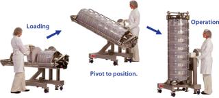
Figure 4: ()
Case Studies
Comparing Stainless Steel Housings and Single-Use Systems: Here, we describe a process improvement program that was implemented with single-use depth filtration. The objective was to replace a two-step, stainless-steel-housing–based “half-thickness, dual-layer media” with a disposable EZP capsule with “full-thickness, dual-layer” depth filter technology.
New biopharmaceutical processes increasingly use full-thickness, dual-layer graded depth filters. Those are made by layering two sheets of filter media of differing pore sizes that are then assembled into lenticular style cartridges. A more open filter is placed upstream to capture large cells and debris, and a tighter filter is placed downstream to remove finer particles such as colloids. Such an approach extends depth filtration capacity and improves protection of downstream membranes, thereby lowering overall filtration costs.
In the current process scheme (Figure 5), 600 L of whole Chinese Hamster ovary (CHO) cell culture is passed through a 10M02 Zeta Plus (3M Purification) dual-layer, half-thickness depth-filter media. The result is passed through a Zeta Plus 60M05 dual-layer, half-thickness media placed in series in 16-in., four-high housings. To determine the optimal EZP single-use filter, our analysis team conducted an initial test with Zeta Plus 60SP05 EXT dual-layer, full-thickness media that were equivalent in filtration ratings to the older “M”-type media. Because the amount of charge the filter carries plays a role in separation, the analysts decided to test a filter media with higher charge capacity compared with the 60SP05 as the second-stage filter. They tested 60ZA05 media — which had a higher charge capacity compared with 60SP05 — as second depth filter. The analysis involved disks installed in 47-mm filter housings and a 3M Purification test kit.
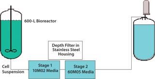
nd-color: #f7f7f7;color:#000000;” >Figure 5: ()
Figure 6 shows results from that evaluation. The first trial with 10M02 media followed by filtration with 60M05 media produced a throughput of 135 L/m2. This value was similar to existing full-scale setup. Results from the “dual-layer” EXT media test (10SP02A followed by 60SP05A in two stages) showed that filtration capacity was still ∼135 L/m2. Because the depth-filter media were thicker, the pressure drop across the two-stage filter train was higher by 5 psid than that of the original filter train. The filtrate with “dual-layer” media exhibited higher clarity with pooled turbidity of 3 NTU versus a turbidity of 5 NTU for the 10M02/60M05 filter combination.
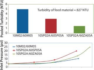
Figure 6: ()
The third trial tested the 60ZA05A following 10SP02A media as a two-step filtration system. Figure 6 shows that the differential pressure across the system was lower and the combination of 10SP02A followed 60ZA05A media produced an even clearer filtrate (pooled turbidity of 1.5 NTU). Based on those results, analysts chose to implement this filter train at full scale.
In the full-scale process, inlet pressures were slightly higher at 5.6–6.0 psi as the flow rate increased and the process ran to a filter capacity of 150 L/m2. The process demonstrated some operational advantages immediately. The stainless steel housings took about nine to 10 hours to set up and complete a depth filtration run; the single-use process set-up and filtration run time was significantly reduced to about three hours.
The process demonstrated other advantages as well. Monitoring capability improved with the single-use process. Operators could “see” the fluid in the filter capsules as a result of the translucent nature of the polycarbonate shell of the EZP capsules. This was especially important during blow-down and postflush. This capability was not possible with the stainless-steel housings. Moreover, set-up and breakdown were easier. Operators did not need to move in winches and other equipment to the manufacturing floor to open large “split-dome” stainless-steel housings.
With the single-use process, operators did not have to install gaskets. No gaskets were lost during set up because the encapsulated cam-lock design contains integral O-rings, and it was easy to confirm that filters were installed and aligned correctly. The set-up allowed operators to vent the core of the filters, which was not possible with stainless-steel housing installation.
Venting the depth filter core prevents air from reaching the downstream membrane and eliminates the need for prolonged venting of a membrane housing/capsule to prevent air-locking.
The encapsulated system also had a much smaller footprint and was ergonomically designed to allow for loading and unloading capsules at waist level. That placed less physical demand on operators for lifting and moving filters.
Enhancing the Life of a Final Membrane Filter: The study involved implementation of a new depth filtration train. The goal was to enhance the life of final 0.2-µm membrane filters. At a major biopharmaceutical manufacturer, a 10,000-L batch of CHO cell culture was processed with a centrifuge. That was followed by a depth filter (four 16-in. × 16 cell Zeta Plus 60ZA lenticular filter cartridges) and by a 0.2-µm membrane filter (Figure 7). The challenge was to develop a filtration scheme to process an entire 10,000-L culture batch (5.4 × 10⁶ cell density, 140 NTU) without changing the downstream 0.2-µm membrane filters.
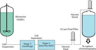
Figure 7: ()
Operators had to change the 0.2-µm membrane filter when it plugged in the middle of the run before the entire batch could be filtered. During the clarification step, the culture drops below the impeller of the stirring system, thereby creating a high cell density at the bottom of the vessel (stirred turbidity of 140 NTU increased to 170 NTU). So the concentrated cell mass presented a clarification challenge for the centrifuge and depth filter.
The first step in developing a solution was to conduct a bench-scale test to determine whether a tighter grade of depth filter would reduce the need to change out the final membranes in the middle of the production run. The study team chose to determine whether a single-layer tighter grade media would work (Zeta Plus 90ZA compared with Zeta Plus 60ZA in the current process).
To do so, they had to establish the turbidity breakthrough point of the 60ZA media. The full-scale process was scaled down using a 47-mm disk (13.5 cm2) of depth-filter media, followed by a final 0.2-µm LifeAssure PDA PES (3M Purification) membrane at a flow rate of 2 mL/min (0.1 L/min/ft2). A throughput of 364 mL would be equivalent to a full-scale throughput of 10,000 L. Initial bench-scale testing indicated no differential pressure build up across the depth filter at a point representing a 5,000-L throughput. Aliquots of filtrate taken during testing, however, indicated a steady increase in turbidity. At a throughput equivalent to 10,000 L, the turbidity was 29.7 NTU, but the 0.2-µm membrane starts to plug when the depth-filter effluent exceeds a turbidity of 10 NTU. So with this filter train, the batch cannot be processed without change-out of the final membrane filter. Analysts determined that sludge (representing
Filtrate quality, however, was still marginal and would not prevent plugging of the final filter (Figure 8). Analysts conducted a second study to determine whether a double-layer, full-thickness EXT format Zeta Plus filter would provide adequate filtration. The team evaluated Zeta Plus 90ZA08A (containing 60ZA/90ZA) and Zeta Plus 120ZA10A (containing 90ZA/120ZA) media. Scaled down from production parameters, the test involved a 47-mm disk (13.5 cm2) at a flow rate of 4 mL/min (0.2 L/min/ft2) followed by a 47-mm disk of 0.2 µm of LifeAssure PDA PES membrane. The success criterion was the same as for the previous study: A throughput of 364 mL (24 L/ft2) must be achieved to be equivalent to a full-scale throughput of 10,000 L.
At the end of filtration, the highest differential pressure on the depth filters was 22 psid. Effluent turbidity of the double-layer 90ZA08A was 32 NTU — similar to the 30 NTU turbidity of the effluent from the single-laye
r 60ZA. That indicates that small particles were able to pass through the tighter-layer 90ZA. So even that could not protect the downstream 0.2-µm membrane. The effluent turbidity of the double-layer 120ZA10A media was 7 NTU, which indicates its suitability in protecting the downstream 0.2-µm membrane. This is also evident from the performance characteristics of the 0.2-µm LifeAssure PDA PES membrane with various prefiltration schemes as shown in Figure 8.
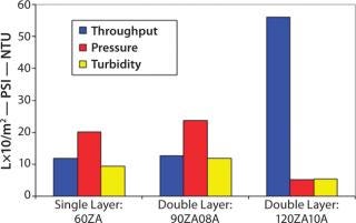
Figure 8: ()
Because the differential pressure across the 120ZA10A media was high, analysts conducted a third test to determine whether a two-step process containing two different double-layer EXT filters in series — Zeta Plus 60ZA05A (contains 30ZA/60ZA media) followed by 90ZA08A (contains 60ZA/90ZA media) — could provide adequate filtration. Bench-scale tests used the same conditions as previous studies. Results showed that using only a single stage of 90ZA08A EXT media produced a final turbidity of 9.0 NTU and a final 0.2-µm membrane differential pressure of 15 psid. By comparison, a two-stage process consisting of 60ZA05A EXT to 90ZA08A EXT filters produced a final turbidity of 4.5 NTU, and the pressure drop across the membrane filer was 6 psid.
The entire 1,000-L batch could now be processed with a large, single-use, depth-filter system involving two stages of depth filtration. The design thus eliminates the need to change a final membrane before the entire batch is processed.
Replace a Centrifuge? Another case study describes replacement of a centrifuge in an existing process for CHO cell culture by a single-use, depth-filter system. The existing clarification process used a centrifuge followed by a single-layer Zeta Plus 60SP depth filter and 0.2-µm membrane filters (Figure 9).
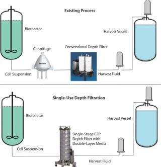
Figure 9: ()
During one harvest run, the continuous stacked-disk centrifuge broke down. Analysts decided to process the batch with only the Zeta Plus filters and the 0.2-µm membranes. Based on a previous success in another process with Zeta Plus EXT media, the team conducted an initial pilot-scale trial with a dual-layer 60SP02A filter. The long-term goal at this processing site was to make all downstream processes single-use. That test fit in the scheme of things. The pilot-scale trial involved an EZP module to process a 1,000-L batch. The differential pressure across the downstream 0.2-µm membrane barely increased at the end of the run (
The 1,000-L batch was filtered with 7 EZP capsules containing Zeta Plus 60SP02A (1.6 m2 per capsule) media with no differential pressure build-up on the downstream 0.2-µm membrane. The Zeta Plus 60SP02A EXT filter was sufficient to protect the final 0.2-µm membrane and produce clean filtrate for downstream purification, thereby removing the centrifuge from the process entirely.
Feedback on the single-use system from the operators reported
minimal residual liquid observed during system break-down, which was a vast improvement over the traditional filtration system installed in stainless-steel housings
easy and convenient set up
significantly reduced cleaning time for equipment and the process suite; no CIP or cleaning validation studies required
shorter cycle times and reduced manufacturing costs.
Product Development
Depth filters are widely used in the bioprocess industry for clarifying cell culture broths. Through the years, they have been an effective and reliable unit operation. Single-use depth filtration is relatively new.
Our company’s product development engineers developed the EZP single-use filters through a deliberate process. Development of which posed several challenges. First, large-scale plastic pressure vessels were designed to house the lenticular cartridges and rated at operating pressures of 50 psi. Plastic mold flow studies and modeling were used to develop the optimal housing design. Because the filters would be connected in series, bioprocess operations required a leak-proof design. So our engineers developed a cam-lock mechanism for sealing individual modules together.
They also evaluated ways to maximize filter area use. A vertical flow path and arrangement was the preferred design. Because those modules contained 1.6 m2 of filter area in each and when wet could weigh over 25 kg (55 lbs), the engineers developed a new racking system. The new design (based on a gear system) allowed horizontal loading and unloading of “depth filter cells” at an operator’s waist level. Those cells can then be maneuvered into a vertical position for running in the process (Figure 4). In this way, the two requirements of maximum filter utility and an ergonomic system design was attained.
Handles were provided on the module at convenient locations for loading and unloading. A voice-of-customer study showed that operators wanted to be able to visually observe product hold-up volume in the housing. As a result, the housing was designed to be translucen, which restricted the choice of plastic to polycarbonate. In addition, some users prefer to use NaOH to sanitize depth filters. So the design team also developed a different polymer-based housing that offered substantial alkaline resistance.
Aditional Applications
Single-use depth-filtration technologies can be used for purposes other than clarification of cell culture streams. Because the depth-filter media can carry a surface charge, depth filters will retain particles smaller than their rated pore size. Studies have shown that depending on process design, Zeta Plus charged depth filters can be used for removing host-cell proteins (9).
The Zeta Plus 120ZA10A media described earlier has a tight particle-retention rating. A presentation demonstrated that the 120ZA media was effective in removing host-cell DNA (hcDNA) from perfusion cell reactor harvests. In that study, feed hcDNA was reduced from 55,968 ng DNA/mg protein to 183 ng hcDNA/mg of protein in the filtrate (10). Depth filters have also been used in orthogonal virus removal steps, providing up to 4-log viral clearance (11)(12). Other studies have shown that charged depth filters removed nonenveloped RNA viruses (such as mouse minute virus) at a process capacity of 320 L/m2 when a feed containing 2% spiked viruses w
as loaded.
About the Author
Author Details
Thomas P. O’Brien is senior applications specialist (retired); Laura A. Brown is a SASS specialist II; Dennis G. Battersby is a field specialist II; Aimee S. Rudolph is a sales engineer; and corresponding author LP Raman is manager of marketing development, all Life Sciences Process Technologies, 3M Purification, 400 Research Parkway, Meriden, CT 06450; 1-203-238 8884; [email protected].
REFERENCES
1.) Schirmer, EB. 2010. Primary Clarification of Very High-Density Cell Culture Harvests By Enhanced Cell Settling. BioProcess Int. 9:34-39.
2.) Russell, E, A Wang, and AS. Rathore Shukla, AA, M and S. 2006.Harvest of a Therapeutic Protein Product from High Cell Density Fermentation Broths: Principles and Case StudyProcess-Scale Bioseparations for the Biopharmaceutical Industry, CRC Press, Boca Raton:1-58.
3.) Shukla, AA, and JR. Kandula Gottschalk, U. 2009.Harvest and Recovery of Monoclonal Antibodies: Cell Removal and Clarification, John Wiley & Sons, New York:53-78.
4.) Singhvi, R. 1996. Clarification of Animal Cell Culture Process Fluids Using Depth Microfiltration. BioPharm 9:35-41.
5.) Quigley, GT. Jornitz, MA and TH 2008.Prefiltration in Biopharmaceutical ProcessesSecond Edition, Informa Healthcare, New York:1-22.
6.) Prashad, M, and K. Tarrach. 2006.Depth Filtration: Cell Clarification of Bioreactor Off loadsFiltr. Sep:28-30.
7.) Hill, P, and J. Bender Stacey, G and J. 2007.Cell Harvesting, John Wiley & Sons, Ltd, Boca Raton:305-330.
8.) Sinclair, A, and M. Monge. 2009. Disposables Cost Contributions: A Sensitivity Analysis. BioPharm Intl. 22.
9.) Yigzaw,. 2006. Exploitation of the Adsorptive Properties of Depth Filters for Host-Cell Protein Removal during Monoclonal Antibody Purification. Biotechnol. Progr. 22:288-296.
10.) Wesner, J. 2008.Reduction of Host-Cell DNA in Mammalian Cell Culture Using Charged Filters at Protein-A Capture for Monoclonal Antibodies, BPI.
11.) Zhou, JX. Gottschalk, U 2008.Orthogonal Virus Clearance Applications in Monoclonal Antibody Production, John Wiley & Sons, Inc, Boca Raton:169-189.
12.) Zhou, JX. 2008. Viral Clearance Using Disposable System in MAb Commercial Downstream Process. Biotechnol. Bioeng. 100:488-496.
You May Also Like
