Sterilizing-Grade Filter Sizing Based on PermeabilitySterilizing-Grade Filter Sizing Based on Permeability
Sterilizing filtration renders biotherapeutics free of biocontamination. In many cases, sterilizing-grade filters also reduce bioburden or facilitate closed or aseptic processing. They are used to filter active pharmaceutical ingredients (APIs), formulated bulk, cell culture media, buffer, additives, process intermediates, and so on. Such applications are often critical for ensuring a successful batch operations.
Nonetheless, a significant amount of time and resources are typically not devoted to establishing filter sizing requirements for “simple” applications such as buffer filtration. Here, we provide a sizing tool to help you estimate filter-size requirements for simple filtration applications. Specifically, we describe of a simple generic sizing tool (KBuf sizing constant) for three different sterilizing-grade filters developed using a generic value of permeability for buffer filtration. We include a quick reference chart for different filters to estimate filter-sizing requirements for fairly nonplugging water-like feed streams.
PRODUCT FOCUS: PROTEINS, ANTIBODIES, PROCESS INTERMEDIATES, APIS
PROCESS FOCUS: FILTRATION
WHO SHOULD READ: PROCESS DEVELOPMENT AND MANUFACTURING
KEYWORDS: BUFFERS, STERILIZATION, FILTER SIZING, PERMEABILITY
LEVEL: INTERMEDIATE
Our Vmax technique has been widely used to describe plugging behavior and estimate filter-size requirements of normal-flow membrane filters in biological filtration applications. Using the technique to estimate filter-size requirements involves some experimental filtration work (with test materials and membrane filters) at constant pressure, followed by simple data analysis. For feed streams, such as buffers, with which plugging is insignificant, membrane permeability becomes the governing parameter for determining filter-size requirements. That process provides an opportunity to closely approximate filter-area requirements on the basis of established “membrane permeability” values. Consequently, users can further simplify the sizing technique and develop a simple “generic” sizing tool. It can provide a quick estimate of the sterile filter area required to filter a specific volume of buffer for any given pressure and time.
Theoretical Basis
Based on the gradual pore-plugging model, the Vmax sizing technique is used to estimate normal-flow filter sizes (1). From the model, we derive Equation 1 for determining the minimum filtration-area requirements for a normal-flow filtration process at constant pressure. In that equation, Amin (m2) is the minimum area needed for the process, VB (L) is the batch volume to be filtered, tB (h) is the filtration time, Vmax (L/m2) represents normalized capacity at time = ∞, and Ji (L/m2h or LMH) is the normalized initial volumetric flow rate (flux).

In the Vmax method, a constant pressure forces fluid through a filter. As the filter plugs, flow through the filter decreases over time. By performing a small-scale Vmax study with a product, we can obtain data of volume over time and calculate key sizing parameters of the model such as Vmax and Ji.
For sterile filtration of plugging fluids (e.g., process intermediates in a recombinant protein purification process), the Vmax or filter capacity values range between 50 and 3,000 L/m2. In this range, the capacity term VB/Vmax contributes significantly to the overall area requirements. For nonplugging fluids (e.g., buffers), the Vmax filter capacity value is very high (>>5,000 L/m2). So the VB/Vmax term is relatively small compared with the VB/Ji × tB term in Equation 1. In such cases, Equation 1 may be reduced to Equation 2, which indicates that buffer filtration sizing may be approximated based on membrane filter permeability and process time.

Darcy’s law describes the flow of a fluid through a porous media (2) and can be applied to determine the flux of buffer (nonplugging fluid) through a membrane filter (Equation 3). In that equation, Ji (L/m2s or m/s) is the flux across the filter, ΔP (Pa) is the differential pressure across the filter, µ (kg/ms2) is the viscosity of the fluid, and R (1/m) is the intrinsic resistance of the membrane.

Darcy’s law can also be expressed in the form shown in Equation 4, where Q = (1/R) is the membrane permeability. Given that the intrinsic resistance of the membrane R cannot be measured directly, the membrane permeability for a solution of viscosity µ, Q′ = Q/µ can be simplified to Equation 5. In that equation, Q’ (L/m2sPa or commonly as L/m2hpsi or LMH/psi) is the permeability of a membrane for a given solution of viscosity µ, Ji (L/m2s or more commonly as L/m2h or LMH is the flux across the filter, and ΔP (Pa or more commonly as psi) is the differential pressure across the filter


By performing a Vmax experiment, for a solution of certain viscosity
(µ) at a given applied pressure, the flux of fluid (Ji) across a filter can be measured, and membrane permeability for the solution (Q′) can be subsequently calculated. Equation 4 implies that fluid viscosity has a direct impact on membrane flux. Fluids of high viscosity may result in lower flux and permeability value.
We can assume that the viscosity of water-like buffers is nearly the same as that of water (µw = 1 cP or 0.001 kg/ms2). Similarly, we can assume the permeability of buffer across a filter Q′ is approximately the same as that of water.So combining Equations 2 and 5 for a water-like buffer leads to Equation 6.

Using Equation 6, we can calculate the minimum filter area required to process a fluid if we know the permeability of the solution for a particular membrane and three process conditions: the batch volume, the process time, and the applied differential pressure applied. Although information about process conditions is generally known, fluid permeability across a particular membrane Q′ can be derived only through Vmax experiments, which an end user may not have access to or time and resources to carry out. Alternatively, a generic permeability Q′ representing most buffers can be used to estimate the minimum filtration area required. We can combine those concepts and express filter permeability and its standard size into a sizing constant, which we refer to as KBuf (described below).
Determination of Generic Permeability
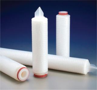
We extracted and analyzed data from our extensive Vmax filtration-sizing experiments (performed by Merck Millipore during process development optimization with nonplugging fluids). We studied three sterilizing-grade filters from Merck Millipore:
Durapore 0.22 µm (CVGL), polyvinylidene fluoride (PVDF) monolayer
Millipore Express SHF (SHF), polyethersulfone (PES) 0.2-µm monolayer
Millipore Express SHC (SHC), polyethersulfone (PES) 0.5/0.2-µm bilayer.
To develop a permeability-based, sterilizing-grade, filter-sizing tool, we compiled data points that exhibit Vmax > 3,000 L/m2 (e.g., nonplugging feed streams) to generate a normal curve for each filter (Figure 1). We took data points from disposable small-scale scaling devices (OptiScale and OptiScale 25) (3). All data points were taken from experimental work with buffers commonly used in the industry. Variability from the mean (standard deviation) — observed for each normal curve — accounts for the total variability and consisted of membrane variability, solution viscosity variability due to temperature effect, and some measurement errors. A generic permeability value Q′g included a safety factor (SF) of 1.3 from the mean of each filter’s normal (Gaussian) curve, and we used it to develop the sizing constant for each filter. An SF of 1.3 is optimal for buffer filtration and represents the trade-off between process robustness and filtration cost (4).

Figure 1: ()
Determination of Sizing Constant
The generic permeability Q′g for each filter selection in Figure 1 applied in Equation 6 provides a quick estimate on the minimum filtration area required. Equation 7 can be used to calculate the number of 10-in. cartridges required based on the calculated minimum filtration area.
By equating Equation 6 to Equation 7, we derived a sizing constant KBuf (Equation 8 and 9) to provide a quick estimate on the number of 10-in. cartridges required to process a certain volume of buffer. KBuf is the sizing constant applied to water-like, nonplugging buffers for a given filter as expressed in Equation 9.


Although data points used to generate KBuf are based on Vmax experimental work on small-scale scaling devices, final filter configuration at manufacturing scale is a pleated filtration device such as a cartridge or a capsule. To account for device format differences, we applied scaling factor (ScF) and inline housing pressure losses of 7% between inlet and outlet inline housing (3) to KBuf to arrive at “KBuf final.” Table 1 lists sizing constants (KBuf final) for each filter type.
Table 1: Sizing constants and formula for sterilizing-grade filters

Table 1: Sizing constants and formula for sterilizing-grade filters ()
The constant (KBuf final) can be directly applied to Equation 8 for water-like fluids (with viscosity similar to µw = 1 cp) or low/nonplugging, clean fluids such as salt dissolved in water for injection and buffers for diafiltration in tangential-flow filtration, precipitation, chromatography, and so on. Alternatively, a quick reference chart (Figure 2) developed using KBuf final constants and filtration time of one hour can be used to estimate filter sizing with reference to applied pressures (5, 10, 15,
or 20 psi) and batch volume. The KBuf final sizing constants or quick reference charts are applicable for all common buffers with viscosity of 1 cp (water-like) at room temperature and little risk of membrane fouling.

Figure 2: ()
The KBuf sizing method (based on KBuf final constants) should not be used if the purity and viscosity of a fluid is in doubt. A quick Vmax sizing assessment should be performed in such situations. Merck Millipore application note (5) includes information about the Vmax sizing experiment. Common buffers used in industry with water-like behavior include those shown in “Common Buffers” box.
Challenging the SizingTool
To verify the accuracy of filter sizing with the KBuf sizing method, we compared filter area obtained from the KBuf sizing method with the filter area obtained using Vmax analysis. We plotted actual volume against time data collected from Vmax experiments, buffers typically used in biopharmaceutical purifications, and common applied pressures required during production. We performed that challenge for each of the three types of sterilizing grade filters: CVGL, SHF, and SHC.
Common Buffers
Common buffers used in industry with water-like behavior include (but not limited to) sodium hydroxide; all citrates, acetate, chlorides, and Tris buffers; phosphate-buffered saline; hydrochloric acid; and acetic acid. All are limited up to 1M and room temperature. This list is taken from a compilation of process development experiments performed by Merck Millipore engineers with buffers on Merck Millipore’s sterile-grade filters.
We intentionally took buffers with permeability similar to Q′mean (calculated from performing a Vmax analysis) to represent buffers with water-like behavior. We did not use buffers exhibiting low permeability (Q′ < Q′g) and high permeability (Q′ > Q′mean) in the analysis. Fluids with permeability <Qg′ could be a result of buffers with concentration >1M. Concentrated solutions will have a viscosity higher than that of water, thereby reducing permeability of solution through a membrane. Buffers with permeability >Q′mean for each membrane could be an artifact of variability in membrane and process conditions such as temperature and viscosity of solution. Because KBuf constant method is primarily developed for sizing water-like buffers, we considered only Q′ = Q′mean for the challenge test. Table 2 shows comparison of filtration area obtained from the Vmax and KBuf method in three case studies.
Table 2: Comparison of Vmax technique and KBuf method sizing (SF = safety factor, Perm. = Permeability)

Table 2: Comparison of Vmax technique and KBuf method sizing (SF = safety factor, Perm. = Permeability) ()
Filtration Sizing Using Vmax Method: We experimentally obtained Vmax and Ji sizing parameters of the gradual pore-plugging model. We used time t and filtrate volumes V of small-scale filtration trials to plot the line t/V = f(V), in which Vmax is the inverse of the slope, and Ji is the inverse of the Y-intercept. We calculated the minimum area Amin needed for the process using Equation 1, experimental Vmax and Ji, process volume, and a one hour process time for comparing both methods.
Using the Amin result, we applied an initial SF = 1.3 (4), appropriate scaling factor of the chosen membrane, and in-line housing pressure loss of 7% (6) to account for the differences between disk and pleated devices. We would then recommend the final process configuration with the available Merck Millipore filtration devices and calculate the overall SF (ratio between the process filter area and the minimum area needed for the process as determined from Vmax calculations).
Filtration sizing withKBufsizing method: Using appropriate reference chart for a given batch volume and applied pressure at production floor, we can estimate the number of 10-in. cartridges for each membrane at a filtration time of one hour. The number of cartridges for filtration times apart from one hour should be accounted for accordingly. For example, if the filtration time is two hours, then the number of cartridges would be half the number sized by the reference chart. Conversely, if the filtration time is halved, the process would require twice the number of cartridges. Alternatively, we can estimate the number of cartridges with the equation for KBuf sizing method found in Table 1 for each filter type by applying the batch volume, time, and applied pressure to the equation.
Case Study: To filter 5,000 L of NaHS buffer using a Durapore CVGL filter in one hour at 10 psi applied pressure, two different methods can be used to size the number of cartridges required for processing the volume of buffer. By using our Vmax method (performing a small-scale trial) the minimum filtration area (Amin) required is 1.93 m2. Considering an SF of 1.3, scaling factor (scaling factor for Durapore is 0.0069), and in-line housing pressure loss (7%), the final filtration area required would be 3.12 m2. So the actual calculated number of 10-in. cartridges required would be five units of Durapore filter. Given that a 10-in. Durapore cartridge has an area of 0.69 m2, five units of 10-in. cartridges will provide 3.45 m2, resulting in overall SF = 1.8.
The KBuf method also can be used to find the filtration area. From the quick reference chart of Durapore CVGL (Figure 2A), we can derive that approximately four units of 10-in. cartridges would be sufficient to perform filtration of 5,000 L of a given buffer. This configuration will result in an overall SF = 1.4 relative to the calculated Amin value from the Vmax trial. Comparision of Vmax and KBuf methods indicate that the KBuf method results in 20% less filtration than Vmax
sizing to process a given volume of buffer.
Table 2 compares filtration areas sized using the Vmax and KBuf sizing methods. KBuf method sizing results were very similar to those of the Vmax method for the three sterilizing-grade filters. KBuf sizing method results were within 20% of Vmax results and had an overall SF of 1.4 to 2, which may be considered acceptable. The above discussion and comparative data analysis indicate that the KBuf sizing method provides a reasonable approximation of sterile filter sizing for buffer filtration applications.
Applying KBuf
The KBuf sizing method applies to only the sterilizing-grade filters Durapore CVGL, Millipore Express SHF, and Millipore Express SHC discussed here. Other sterilizing-grade filters or small-scale devices may not provide similar sizing results because of a difference in membrane permeability and device scaling factors (3). Some screening devices in particular may demonstrate a difference of 53% in normalized permeability between pleated cartridges and flat-sheet devices (7). The KBuf sizing method can be applied only for nonplugging solutions at room temperature with viscosities similar to that of water. The method takes into account in-line housing pressure losses of 7% (3) but does not include other process considerations such as piping and system effects. Plant piping such as elbows and valves, head pressure due to elevation of filters or tanks, and other restrictions such as housing design (e.g., in-line versus T-line) can modify the effective pressure applied to a filter, resulting in longer process times. Additional safety factors or increasing applied pressure to a filter assembly to increase effective pressure across a filter may be considered to overcome the effect of system and piping losses (8).
The KBuf sizing method can be applied to viscous, nonplugging buffers by adjusting the sizing with the viscosity factor (µ/µw = viscosity of fluid ÷ viscosity of water). To ascertain the application of the KBuf sizing method to viscous nonplugging solutions, more experimental data must be generated to to verify the effect of fluid viscosity.
An Effective Technique
A simple sizing method KBuf has been developed and shown to closely approximate filter-sizing requirements for sterile buffer-filtration applications. The filter area configuration suggested by that sizing method is similar (within 20%) to the configuration obtained from a Vmax sizing model. The overall safety factors, around filtration area, ranged from 1.4 to 2 with the KBuf method.
The KBuf sizing method is limited to nonplugging buffers with viscosity similar to water and is applicable to estimate buffer filter-sizing requirements for Merck Millipore’s sterilizing-grade filters Durapore CVGL, Millipore Express SHF, and Millipore Express SHC. The method provides a good estimate of the filtration area required for buffer filtration. Other filtration considerations such as process impacts from a fluid’s characteristics (e.g., purity, viscosity, temperature), piping, and system design should be included when making final recommendations.
Vmax, Express SHC, Express SHF, Durapore CVGL, and OptiScale are proprietary brand names.
About the Author
Author Details
Yanglin Mok is senior process engineer of Merck Millipore, Singapore; Lise Besnard is process development scientist at Merck Millipore, France; Priyabrata Pattnaik, PhD is technical manager of biomanufacturing sciences network at Merck Millipore, Singapore; and corresponding author Bala Raghunath, PhD is director of Asia biomanufacturing sciences network; at Merck Millipore, Biomanufacturing Sciences and Training Centre, 1 Science Park Road, #02-10/11 The Capricorn, Singapore 117528; 65-6403-5308; fax 65-6403-5322; [email protected].
REFERENCES
1.) Merck Millipore Application Note The Vmax™ Nomograph.
2.) Lenchi, RW, and S. Williams. 1995. Effect of Nonaqueous Solvents on the Flux Behavior of Ultrafiltration Membranes. J. Membrane Sci. 101:43-51.
3.) Giglia, S. 2010. Improving the Accuracy of Scaling from Discs to Cartridges for Dead End Microfiltration of Biological Fluids. J. Membrane Sci. 365:347-355.
4.) Lutz, H. 2009. Rationally Defined Safety Factors for Filter Sizing. J. Membrane Sci. 341:268-278.
5.) Merck Millipore Application Note Filter Sizing Methods.
6.) Giglia, S., and D. Yavorsky. 2007. Scaling from Disc to Pleated Devices. PDA J Pharm.Sci. Technol. 61:314-323.
7.) Brown, AI. 2008. Membrane Pleating Effects in 0.2-μm Rated Microfiltration Cartridges. J. Membrane Sci. 341:76-83.
8.) Royce, J, and R. Wilkins. 2006. Considerations for Sizing and Selecting Sterile Buffer Filters.
You May Also Like


