PAT-Based In-Line Buffer DilutionPAT-Based In-Line Buffer Dilution
Technological advancement has taken protein expression titers from concentrations measured in mg/L to those measured in g/L over just a few years (1). Annual demand for antibodies has reached several metric tons, which has spurred production of >100 kg batches of protein at a time (2). As upstream yields continue to increase, downstream purification involving process solution preparation and delivery must increase in proportion to keep pace with demand. That has placed facility and instrumentation capacity constraints front and center in the biomanufacturing industry, where many are directing resources toward eliminating the resulting bottlenecks through increased productivity and efficiency of downstream unit operations (1,2).
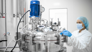
As shown in Photo 1, in-line buffer dilution (IBD) technology has emerged as a process analytical technology (PAT) solution to this dilemma (3). This technology is based on in-line mixing of buffer concentrates (typically 10×) with a diluent (often water) to yield a 1× product. Buffer concentrates eliminate the need for large buffer tank “farms,” which can be replaced by disposable bioprocess bags (2,4). Because a dilution ratio of 100:1 is often achieved with accuracy, the equipment used for an IBD process is compact and can prepare tens of thousands of liters of buffer per hour in a footprint 2.
Photo 1:
PRODUCT FOCUS: ALL BIOLOGICS
PROCESS FOCUS: UPSTREAM AND DOWNSTREAM PROCESSING
WHO SHOULD READ: PROCESS AND PRODUCT DEVELOPMENT, VALIDATION, REGULATORY AFFAIRS, AND MANUFACTURING PERSONNEL
KEYWORDS: BUFFERS, PH, PROCESS CONTROL, CONDUCTIVITY, MASS FLOW, DESIGN SPACE, CHROMATOGRAPHY
LEVEL: INTRODUCTION
IBD technology can be greatly enhanced by engineering PAT-based feedback control into a processing system. Both economic benefits and regulatory benefits can be realized from this engineering advance. In recent years the US Food and Drug Administration (FDA) has encouraged incorporation of the quality-by-design (QbD) paradigm into manufacturing strategies by the biopharmaceutical industry (5). The basic idea of QbD is to first generate a knowledge base about the quality attributes of raw materials used in a process, then to use that knowledge to control critical operational parameters (COPs) and ensure consistent, predictable final product quality (6). A key component of QbD is defining and operating within a “design space” for each manufacturing process. Design space describes acceptable limits for COPs (4,7). And PAT provides the critical means for achieving QbD because it allows manufacturers to enhance understanding of their processes through real-time monitoring and to maintain processes within control limits (4,8).
PAT-based IBD technology can be used for accurately blending process-scale quantities of buffers with various goals in mind, so different design spaces can be constructed relative to a given process. IBD systems can be used to produce buffers
for further downstream processing steps of target compounds (e.g., equilibration, elution, and wash buffers used in protein and/or oligonucleotide purification)
to produce formulation buffers for final product preparation(s) (e.g., injectables such as monoclonal antibodies and vaccines)
as an end product in themselves (e.g., eye drops, contact lens solutions, cough syrups, and biofuels).
An additional opportunity exists for in-line pH adjustment and/or dilution of in-process or final products (such as protein A eluates of purified proteins) and for pH adjustment in viral deactivation.
PAT-Based IBD Technology in a QbD Context: To understand how TechniKrom’s patented IBD technology fits into the QbD paradigm, it’s useful to briefly preview the basic technology platform in reference to the concept of design space (4,8,9). Photo 2 shows a sample piping and instrumentation diagram (P&ID) from the process control screen of an IBD skid.
Photo 2:
Normally, deionized water for injection (WFI) is connected to pump A (P001), and a 10× concentrate of salt buffer is connected to pump B (P002). WFI and buffer concentrate are then pumped into a mixing loop, where the buffer concentrate is diluted down to 1×. Its molarity has a specific conductivity that can be monitored and controlled by an in-line process analyzer (conductivity sensor) that interfaces with a process control feedback loop. The sensor continually monitors conductivity of the buffer blend in the mixing loop and sends an output signal to the process control feedback loop. That loop then references the current process value to a user-defined conductivity target set-point for the 1× buffer. It sends a signal to adjust the pump speeds accordingly so that the dynamic ratio of WFI to salt buffer in the mixing loop is continually adjusted toward the set-point.
When conductivity is sufficiently close to the set-point (within specification), buffer is released to a product collection vessel. When the buffer is not within specification, it is diverted to waste until the conductivity process value comes back into spec. So process conditions are always known, and no out-of-spec buffer goes to the product. In a design space, process specifications are obtained through process development and characterization of buffer critical quality attributes (CQAs) (7,8). Based on that knowledge, an acceptable range of conductivity can be established. The boundaries of that acceptable range are its upper and lower control limits (UCL, LCL), which define the design space. In an IBD system, the mean between those limits is the conductivity process set-point (8). Maintaining the buffer within specification keeps a process within its design space, so it is simultaneously validated. Once sufficient validation is shown, regulatory filing of the design space can be accomplished. In future runs, simply recording the buffer blend as it is maintained within the design space (or as it is diverted to waste when out of design space) is considered to be sufficient validation of product quality assurance (8,9). This eliminates the enormous resources invested into post-run QC analysis.
For simplicity, a binary blending configuration is presented above. However, additional levels of complexity are often incorporated such as using a pump C (P101) for buffer pH adjustment. In such a case, a pH probe would be installed in the mixing loop that interfaces with its own process control feedback loop to drive the solution pH toward a user-defined set-point. This arrangement comprises a ternary blend in which both the pH and conductivity of a buffer are adaptively and simultaneously controlled by independent process control feedback loops.
This patented technology is often engineered into the front end of a process-scale liquid chromatography (LC) skid, in which a series of buffers are made on demand and sent directly to a process column for a sequence of chromatography steps in a purification regime. In this case, UCL and LCL are defined for a design space of each buffer for each chromatography step. Only buffers that fall within their design space control limits are sent to the column. When a buffer is not within specification, it is diverted to waste until conductivity and/or pH values come back into spec. This guarantees that no out-of-spec buffer will reach the column, so it can’t negatively affect the efficiency of the chromatographic profile.
The ability to monitor and control the process values of conductivity and pH in real time using PAT provides for process robustness and can help companies adaptively adjust to variability in raw material buffer feed stocks. So an IBD-controlled process can provide consistent and predictable quality assurance, with quality built in to the process itself and operating within the design space provides on-the-spot validation (7,8). Optimally, when the design phase of a PAT-based IBD process includes application of six sigma and failure mode and effect analysis (FMEA), the full economic and regulatory benefits can be realized (10).
For our study, we chose a statement from the FDA’s PAT guidance as a standard for assessing the validity of using in-line buffer dilution with pH and conductivity adaptive feedback control in QbD manufacturing of bioprocess buffers:
Process monitoring and control strategies are intended to monitor the state of a process and actively manipulate it to maintain a desired state. Strategies should accommodate the attributes of input materials, the ability and reliability of process analyzers to measure critical attributes, and the achievement of process end points to ensure consistent quality of the output materials and the final product. (11)
To assess the capability of an IBD system “to monitor and manipulate the state of a process and actively manipulate it to maintain a desired state” (11), we performed two buffer blending experiments. The first involved design and creation of a binary blend (conducted to produce 10 mM sodium phosphate and 20 mM NaCl at pH 7 from a 10× concentrate) with the goal of monitoring and controlling the conductivity of the 1× buffer within upper and lower control limits for an hour. The second experiment went a step further and was designed to create a ternary blend to produce a 1× Tris acetate buffer from 10× concentrates of Tris base and acetic acid. The goal of that experiment was to monitor and control both pH and conductivity of the 1× buffer.
Both blends also addressed the aspect of the FDA’s statement that deals with “accommodating the attributes of input materials” (11). The 10× concentrates were intentionally prepared in a casual manner so that exact starting concentrations would not be known. Next, experiments were designed to test “the ability and reliability of the process analyzers to measure critical attributes” by performing stability, sensitivity, and temperature variation studies on the process analyzers.
Materials
Sensor Stability and Temperature Compensation Testing: Most instruments used for these experiments were standard components on a 5-L/min IBD skid from Asahi Kasei TechniKrom, Inc. (www.technikrom.com) as shown in Photo 1. The pH probe was an ABB Limit model #AP121 21000 electrolyte-filled glass electrode from ABB Instrumentation (w3ww.abb.com). The conductivity sensor was an Optek CF60-45 (six electrodes) with a Pt1000 platinum resistance temperature device (RTD) used for temperature measurement and compensation from optek-Danulat (www.optek.com).
Both probes were mounted in a 1-in. F40 Optek Peek flow cell with a PF12 pH electrode adapter. An Optek Control 200 controller was installed on the skid and used as a dual-input electrochemical converter to monitor pH, conductivity, and temperature. Conductivity, pH, and temperature output signals from the electrochemical converter were processed and trended in a run chart using Proficy HMI/SCADA–iFIX and Proficy Historian version 3.1a software with SP1 process control software from GE Fanuc (www.gefanuc.com) on a personal computer housed in the skid. Oakton Instruments’ pH and conductivity standards were used for sensor calibration (www.4oakton.com).
Temperature control and buffer recirculation were achieved using a programmable Polyscience model 9712 thermal bath (www.polyscience.com). Bioprocess buffers (1×) were prepared by hand. Raw materials were carefully weighed out using a model JK-200 analytical digital balance, from Chyo Balance Corporation (Komatsu, Japan) with 0.01-mg accuracy, then dissolved in deionized water. Monobasic and dibasic sodium phosphate, sodium chloride, glacial acetic acid, and Tris base came from Amresco Inc. (www.amresco-inc.com).
Binary and Ternary Blending Experiments: For making buffers using patented IBD adaptive blending controlled by conductivity and/or pH, we used a 5-L/min IBD skid equipped with process analyzers and software as referenced above. Standards (1 L each) of 1× bioprocess buffers were carefully and accurately prepared as described above. Bioprocess buffer concentrates (~10×) were prepared by hand. Raw materials were casually weighed out using a model MK-2000B Petit balance from Chyo Balance Corporation with 0.1-g accuracy, then dissolved into ~80 L of deionized water in polycarbonate drums. Mono- and dibasic sodium phosphate and sodium chloride came from Sigma-Aldrich (www.sigmaaldrich.com). We determined temperature compensation factors for the various buffers using the process flow cell with conductivity and pH sensors from the IBD skid placed in-line with the Polyscience recirculating thermal bath.
Methods
Sensor Stability and Temperature Compensation Testing: To test for stability and/or inherent drift in the process analyzers, we subjected the pH and conductivity sensors to 72 hours of continuous buffer recirculation under isothermal conditions using a thermally controlled recirculation bath. Both probes were first installed in the process flow cell, then connected to an electrochemical converter. We calibrated them according to their manufacturers’ specifications using calibration standards chosen to bracket the pH and conductivity values of the recirculation buffer.
After calibration, we removed the process flow cell and installed it in-line in the recirculation thermal bath filled with 10 mM sodium phosphate and 20 mM sodium chloride at pH 7.0. For the sensor stability test, we set the temperature to 20 °C and recirculated the sodium-phosphate buffer through the process flow cell at ~8 L/min, holding the temperature constant and recording data for temperature, conductivity, and pH over 72 hours.
To evaluate temperature compensation, we used the same buffer, instrument configuration, and data collection regime as above but ran a temperature gradient from 18.77 to 23.25 °C over 130 minutes (▵T/min 0.035 °C/min). The pH sensor contained a Pt 100 ohm RTD within the glass electrode, and pH temperature compensation was automatically performed by the Optek electrochemical converter using the Nernst Equation, which is standard for most modern pH instrumentation (13). The conductivity sensor contained a Pt 100 ohm RTD as well, and conductivity temperature compensation was performed by the Optek Control 200 converter using a factory setting for NaCI of 2.0% per °C.
Binary and Ternary Blending Experiments: Before producing the binary and ternary blends of sodium phosphate and Tris-acetate buffers, we experimentally determined the conductivity temperature compensation factor (TCF) for each. First we removed the process flow cell and connected it to the inlet and outlet tubing of the recirculating thermal bath in an identical configuration to that explained above. The thermal bath was filled with the appropriate buffer and its temperature raised and lowered incrementally while buffer was recirculated through the flow cell at ~8 L/min. During the incremental temperature steps, we kept the conductivity TCF for the Optek electrochemical converter set to none. While varying the temperature, we recorded conductivity values for each buffer and entered them into the following equation for calculating the TCF with units of % per °C:
Gt1 and Gt2 are conductivity readings at the initial and final temperatures, respectively. The initial and final temperatures were entered into the formula as t1 and t2 respectively. After TCF was determined for a particular buffer, its value for % per °C was entered into the Optek electrochemical converter as a user-defined value for conductivity temperature compensation. Finally, we changed the temperature of the buffer incrementally as before then recorded and graphed the new temperature-compensated conductivity readings (Figure 3).
For the binary blend experiment, we carefully prepared a 1-L standard of 10 mM sodium phosphate at pH 6.7 by accurately weighing the raw materials using an analytical digital balance (0.01-mg accuracy), then dissolved them in 1 L of deionized water. After thorough mixing, we poured the buffer standard into the process flow cell (with capped ends) and recorded conductivity readings in triplicate or until the reading stabilized. We took that stable reading as the conductivity set point for the 10 mM sodium phosphate, pH 6.7 buffer blending experiment.
Next, we connected the outlet tubing of the polycarbonate drum containing 10× buffer concentrate (~100 mM sodium phosphate at pH 6.7) to pump B of the IBD skid and connected another drum containing deionized WFI to pump A. Then we programmed a method into the Proficy iFIX process control software with our previously determined conductivity reading for the buffer standard as the conductivity set-point. We set the flow rate at 0.5 L/min.
That method was initiated as an “optimization” run, during which we tuned the PID parameters for that buffer, and the automated process control loops adaptively blended the WFI and concentrate until the conductivity process value stabilized at its set-point. After several minutes of the system remaining in control (within specification), we recorded the WFI, concentrate, and mixing loop pump speeds and entered them into a new method as pump preset start speeds with a 15-second hold time. The run was then terminated and the new program downloaded and initiated. At the beginning of the run, the pumps started off at their preset start speeds and were held there for 15 seconds. After that, the system switched into automatic PID control for the remainder of a one-hour run.
For the ternary blend experiment, the equipment and procedures were the same as outlined for the binary blend experiment with the following exceptions: The target buffer was 216 mM Tris and 284 mM acetate at pH 5.04; 1 M acetic acid was connected to pump B, and 1 M Tris base was connected to pump C; and the flow rate was set at 2 L/min.
Sensitivity Test: To test sensor sensitivity, we produced an extremely dilute buffer (2.5 mM Tris and 27.5 mM acetate at pH 3.83) using the method described above for the ternary blend experiment.
Results
Sensor Stability Testing: To evaluate sensor stability of the process analyzers and test for susceptibility to drift, we subjected the sensors to a 72-hour isothermic recirculation of sodium-phosphate buffer. Results of this test showed that the pH and conductivity sensors were stable over the 72-hour run, without exhibiting observable drift (Figure 1). The flow cell was connected to the inlet and outlet tubing of the recirculation bath, situating it outside the bath itself, so some heat exchange occurred between the environment and the tubing and allowed some temperature variation during the run (±0.77 °C). Initial conductivity of the sodium-phosphate buffer was 5.80 mS/cm; final conductivity after 72 hours was 5.81 mS/cm, indicating negligible sensor drift. Additionally, temperature-dependent fluctuations in conductivity or pH during the run were less than ±0.1 mS/cm and 0.1 pH units, respectively.
Temperature Compensation Testing: To evaluate the viability of temperature compensation with conductivity and pH-based, PAT-controlled, in-line buffer dilution, we subjected the pH and conductivity sensors of the process analyzers to a temperature gradient of 4.5 °C over 130 minutes in the same configuration as above (Figure 2). Temperature compensation was successful for both conductivity and pH. Although the temperature varied by 4.5 °C, both conductivity (0.06 mS/cm) and pH (0.01 units) stayed relatively flat over the course of the temperature gradient.
Binary and Ternary Blending Experiments: The formula for calculating the conductivity temperature compensation factor (Equation 1) was used for the sodium phosphate and the Tris acetate buffers. Once the calculated TCFs were applied to the Optek electrochemical converter, the temperature of the sodium phosphate (data not shown) and Tris acetate (Figure 3) buffers could be varied without significantly changing conductivity. As Figure 3 shows, temperature-compensated conductivity for the Tris acetate buffer was flat (well compensated) between 20 and 25 °C, but above 30 °C it began to shift upward and followed the temperature curve.
Binary Blending Experiment: The 1-L standard of 10 mM sodium phosphate at pH 6.7 gave a reading of 1.42 mS/cm, which we used as the programmed conductivity set-point in the process control software. We set the conductivity detector range from 0 to 100 mS/cm to correspond to 4–20 mV of output, and we set the conductivity specification limits to ±0.1% of the range of the detector, which came out to ±0.1 mS/cm from set-point. After recording the pump speeds that gave in-spec buffer during the optimization run, we stopped the run with the IBD system fully equilibrated. Then we initiated a new run with the same pump speeds that were recorded at the end of that optimization run. In our “product run,” buffer conductivity began in spec (Figure 4). After a 15-second hold at the preset pump start speeds, the process control loops switched into automatic mode and maintained buffer conductivity within specification for the entire run (one hour).
Ternary Blending Experiment: The 1-L standard 216 mM Tris and 284 mM acetate gave a conductivity reading of 9.42 mS/cm and a pH reading of 5.04, which we used as programmed conductivity and pH set-points. We determined specification limits as for the binary blend and established ±0.1 mS/cm and ±0.1 pH units from the set-points. We performed an optimization run as above, and the product run yielded in-spec buffer for both conductivity and pH throughout the one-hour run (Figure 5).
Sensitivity Test: To test sensitivity of the IBD unit to control conductivity within the mS/cm range, we used a dilute version of the Tris-acetate buffer. A 1-L standard of dilute 2.5 mM Tris and 27.5 mM acetate yielded conductivity and pH set points of 237 µS/cm and 3.83 pH units. In this instance, the conductivity detector range was 0–1,000 µS/cm for the output span of 4–20 mV. During the optimization run, the system was unable to control conductivity within ±1 µS/cm of set point (data not shown), which would have constituted ±0.1% of the detector range. So we increased the specification limit tenfold to ±10 µS/cm of set-point. With that adjustment, optimization and product runs yielded in-spec buffer for an hour (Figure 6). The lower limit of sensitivity for this instrument thus can be considered at ±0.1% of the conductivity range to a minimum of ±10 µS/cm of the set-point.
Discussion
Sensor Stability and Temperature Compensation Testing: The FDA’s PAT guidance states, “Design and construction of the process equipment, the analyzer, and their interfaces are critical to ensure that collected data are relevant and representative of process and product attributes” (11). We conducted these experiments to test the robustness of our conductivity and pH sensors, showing that the process analyzers provide stable readouts devoid of inherent drift (Figure 1). In addition, both sensors proved capable of adequate temperature compensation (Figure 2), which is critical for minimizing susceptibility of sensor data to environmental or instrumental temperature variations.
Figure 3 shows the ability of the Optek electrochemical converter to accommodate user-defined conductivity temperature compensation factors for unique buffers. The conductivity trend for the Tris acetate buffer was level (therefore well compensated) between 20 and 25 °C. Such highly accurate performance provides confidence in the data from the blending experiments. Our observation that conductivity compensation was less robust above 30 °C should be of minor consequence for most users, however, because 20–25 °C is the relevant temperature range for most temperature-controlled manufacturing facilities.
Sensitivity Test: In addition to demonstrating robust performance, the process analyzers were also shown to have extremely low limits of detection for process-scale applications. Figure 6 shows that our PAT-based IBD system was fully capable of monitoring and controlling conductivity of Tris-acetate buffer in the µS/cm range. Indeed, the system comfortably operated within a design space of ±10 µS/cm for conductivity and ±0.1 pH units. That degree of sensitivity is crucial for the biopharmaceutical industry, in which chromatographic performance often depends on extremely tight specification ranges for CQAs and parameters (2). Our data on sensor stability, sensitivity, and temperature compensation capability of the process analyzers provide key evidence to ensure that the process control feedback loops are not driving pump speeds based on biased data readings. That ensures that final product data can be used for validation with confidence.
Binary and Ternary Blending Experiments: As shown in both our binary (Figure 4) and ternary (Figure 5) blending experiments, the PAT-based IBD system was able to monitor and adjust either conductivity alone or conductivity and pH simultaneously to maintain the desired state (control set points) throughout a one-hour run. The system operated successfully within the design space despite the fact that the concentrations of 10× concentrates (input materials) were not accurately prepared. This PAT performance level is aligned with the goal of QbD for a process to accommodate variability in the attributes of input materials (11).
Process Analyzers: Two principal strategies have emerged for biopharmaceutical buffer preparation with an IBD system. The critical difference between them is in the choice of process analyzers for feedback control of buffer blending: mass flow meters or a combination of pH and conductivity meters. The essential distinction between these types of monitoring is either direct or indirect measurement of physicochemical properties that are proportional to the quantity of raw materials in the buffer feed stocks.
Measurements such as pH, conductivity, near-infrared (NIR), Raman, ultraviolet (UV), dissolved oxygen (DO), refractive index, and rapid bioassays are examples of process analytical tools that directly measure physicochemical properties in real-time that are directly proportional to the quantity of raw materials. By contrast, measuring flow rate with a mass-flow meter is an indirect measurement of the quantity of raw materials present. When such measurement is used for quantitative analysis, the raw material quantities have to be back-calculated based on measurements performed off-line and in the past. According to the FDA’s QbD initiative, “Process monitoring and control strategies are intended to monitor the state of a process and actively manipulate it to maintain a desired state. Strategies should accommodate the attributes of input materials, the ability and reliability of process analyzers to measure critical attributes” (11).
The most suitable process analyzers for process feedback control are those that provide direct quantitative analysis of input material attributes such as conductivity and pH. Using conductivity and pH process analyzers allows for development of UCLs and LCLs based on actual physicochemical attributes of the buffer feed stocks (e.g., ±0.1 µS/cm and ±0.1 pH units) that define the all-important design space in QbD manufacturing. When a process state is actively manipulated based on direct, realtime quantification of physicochemical attributes, buffer concentrate molarities can be variable and actively brought to within specification control limits by automated feed-back control.
By contrast, when mass flow meters are used to control buffer dilution, prepared input materials (buffer concentrates) must accurately match target set-points because the process cannot be manipulated and controlled based on physicochemical properties of the input materials (2). So any design space developed for in-line buffer dilution based on mass flow measurements cannot aptly provide assurance of quality by itself. The limits of the design space thus do not provide the basis of validation acceptance criteria as outlined by Anurag et al. (7). Such a lack of quality assurance within a design space creates increased reliance on off-line measurements of buffer concentrates for process validation, which does not align with the goals of PAT-based QbD manufacturing. Off-line validation also creates added manufacturing costs for quality analysis of buffer concentrates. Capital is lost to disposal of nonconforming preparations of buffer concentrates.
The ideal PAT-based IBD manufacturing state is one in which design space is defined by specification limits based on buffer physicochemical attributes such as conductivity and pH, which in turn serve as process validation acceptance criteria. This ensures that quality is directly designed into a process rather than being indirectly “tested into” it through off-line quality control.
REFERENCES
1.) McLeod, LD. 2009. The Road to a Fully Disposable Protein Purification Process: Single-Use Systems Eliminate Time-Consuming, Non–Revenue-Generating Activities. BioProcess Int. 7:S4-S8.
2.) Matthews, T. 2009.Pharmaceutical Buffer: An Integrated Approach to Buffer Dilution and Storage Pharmaceut. Mfg..
3.) Bellafiore, L. 2008. In Line Buffer Dilution: The “Killer App” for Process Analytical Technology. BioProcess Int. 6:106.
4.) Walker, J. 2006. Kick-Starting PAT to Achieve Quality By Design in cGMP Bioprocessing, TechniKrom, Inc., Evanston.
5.) ICH Q8, R2 2006. Pharmaceutical Development. Fed. Reg. www.ich.org/LOB/media/MEDIA4986.pdf 71.
6.) Rathore, AS. 2008.Quality By Design: Industrial Case Studies on Defining and Implementing Design Space for Pharmaceutical Processes — Part 1BioPharm Int..
7.) Rathore, AS, R Branning, and D. Cecchini. 2007.Design Space for Biotech ProductsBioPharm Int.:36-40.
8.) Rathore, AS. 2008.Quality By Design: Industrial Case Studies on Defining and Implementing Design Space for Pharmaceutical Processes — Part 2BioPharm Int..
9.) Konold, P. 2009.Monitoring of Biopharmaceutical Processes: Present and Future ApproachesBioPharm Int..
10.) Henretta, K, J Walker, and L. Bellafiore. 2003. Applying Six Sigma to Chromatography, a Tutorial: Cutting Costs through Process Improvements. Gen. Eng. News 23.
11.) CBER/CDER 2004.PAT Guidance for Industry: A Framework for Innovative Pharmaceutical Development, Manufacturing and Quality Assurance, US Food and Drug Administration, Rockville.
You May Also Like
